background image

IG-175-EN version 02; 17/06/2016

28

Installation and connections  

General Instructions

ekor.gid 

6.2.  ekor.gid connections

6.2.1.  Wall-mounted

Once the ekor.gid unit has been installed on the wall, the 

general connections are carried out, which are required to 

carry out the remote reading of the Low Voltage meters. 

These connections are the following: 

1.  4 voltage signals (3P+N) per each Low Voltage board to 

be monitored (and therefore, per Medium / Low Voltage 

transformer in the Substation), with a maximum of 

2 boards in the ekor.gid unit. This wiring comes from 

the Low Voltage board and is connected to each of 

the two voltage connectors available on the ekor.gid 

unit, where preferably the left connector is used for 

transformer 1 and the right one for transformer 2. 

2.  6 voltage signals (Ia1-Ia2, Ib1-Ib2, Ic1-Ic2) per each Low 

Voltage board to be monitored (and therefore, per 

Medium / Low Voltage transformer in the Substation), 

with a maximum of 2 boards in the ekor.gid. This wiring 

comes from the Low Voltage board and is fed through 

the packing gland located in the lower part of the 

cabinet, to the disconnectable and short-circuitable 

terminals of the ekor.gid unit. 
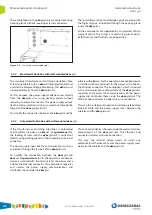
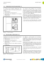
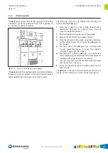
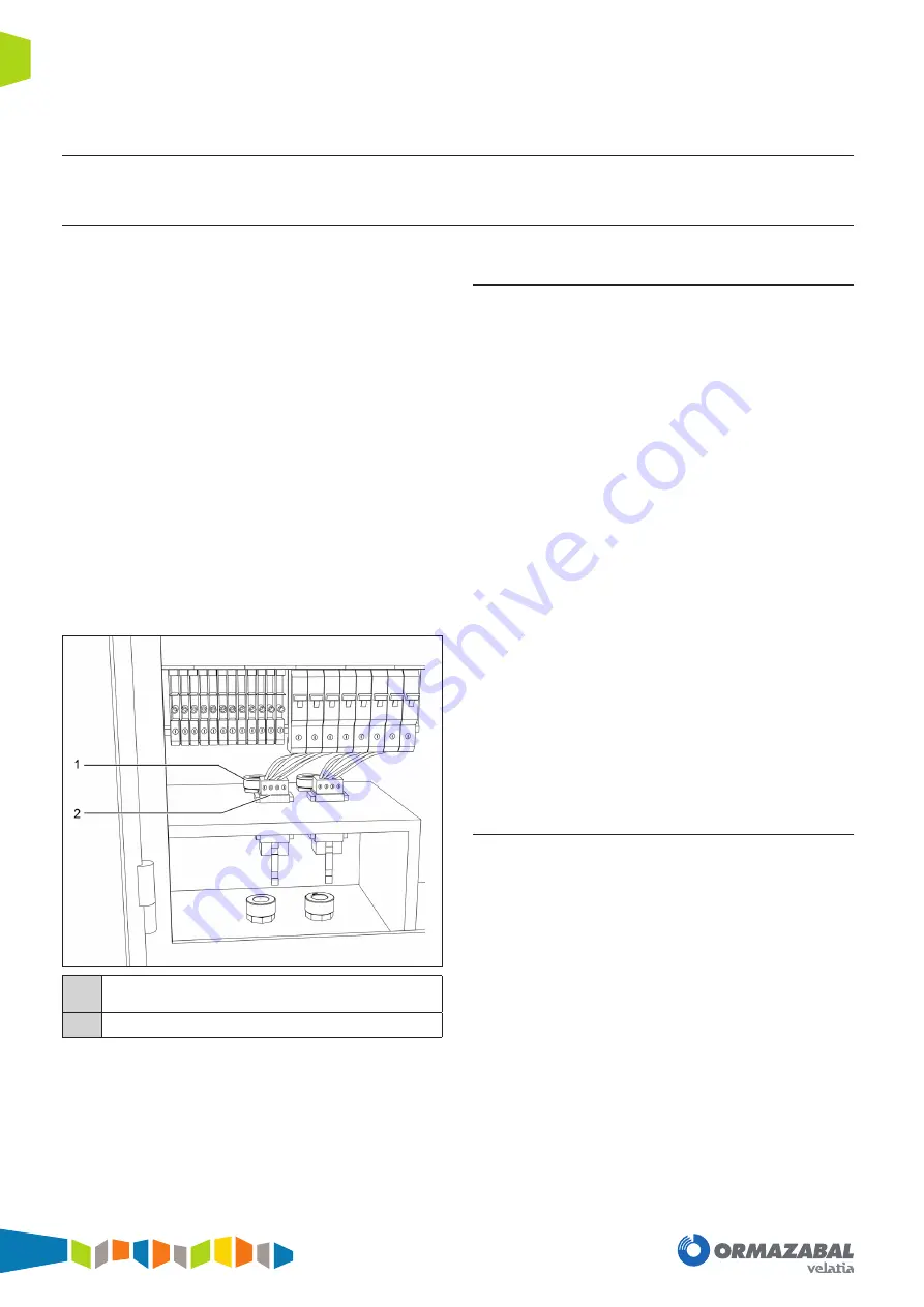
1

Packing gland for feedthrough of current signals and its 
connection to disconnectable and short-circuitable terminals

2

Voltage connectors

Figure 6.3. 

Low Voltage Compartment connections

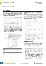
Connections for the Monitoring of the Medium Voltage 

network

In the event that the Substation is Monitored, in addition 

to the general connections, the following connections 

between the ekor.gid unit and the corresponding 

Monitoring cubicle must be carried out: 

1.  Two power supply wires (+48 V

DC

 / 0 V) to feed the 

Medium Voltage network relays, which come out of a 

packing gland in the Communications Compartment of 

the ekor.gid unit and go to the Monitoring cubicle. This 

circuit is protected by a miniature circuit-breaker.

2.  Two wires (+48 V

DC

 / 0 V

DC

) that come out of a packing 

gland in the Communications Compartment of the 

ekor.gid unit and supply the protection cubicle trip 

circuit. This circuit is protected by a miniature circuit-

breaker.

3.  An Ethernet cable sheath with 8 wires, prefabricated 

and ending on both sides with an RJ-45 connector, 

which on one side is connected to the ekor.rci  unit of 

the Monitoring cubicle and on the other side to a hub 

located inside the Communications Compartment of 

the ekor.gid unit. The cables are also fed in through the 

packing gland located at the top part.

4.  Two wires (+48 V

DC

 / O V

DC

) for the battery charger 

alarms that come out of a packing gland in the 

Communications Compartment of the ekor.gid unit 

and go to the Monitoring cubicle.

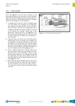
Connections for Automation

In the event that the Substation is Automated, in addition 

to the general connections, the following connections 

between the ekor.gid  unit and the ekor.uct unit or the 

corresponding  cgmcosmos-2lpt cubicle must be carried 

out: 
1.  Two power supply wires (+48 V

DC

 / 0 V) that come out of 

a packing gland in the Communications Compartment 

of the ekor.uct unit or cgmcosmos-2lpt unit and go to 

the  ekor.gid unit, also entering through the packing 

gland in the Communications Compartment of the 

ekor.gid unit. 

2.  An Ethernet cable sheath with 8 wires, prefabricated and 

ending on both sides with an RJ-45 connector, which 

on one side is connected to the ekor.ccp unit of the 

ekor.uct unit or the cgmcosmos-2lpt cubicle and the 

other side to a hub located inside the Communications 

Compartment of the ekor.gid unit. The cables are also 

fed in through the packing gland located at the top 

part. 

Summary of Contents for velatia ekor.gid

Page 1: ...LIB ekor gid Smart distribution management unit General Instructions IG 175 EN version 02 17 06 2016...

Page 2: ...trical installations This personnel must be fully familiar with the instructions and warnings contained in this manual and in other recommendations of a more general nature which are applicable to the...

Page 3: ...4 4 Low Voltage Monitor s 17 3 4 5 Power Supply Equipment depending on the model 17 3 4 6 Ethernet 18 3 4 7 Connection and Protection Components 19 3 5 ekor gid unit interconnections 19 3 5 1 Telemana...

Page 4: ...ults in fewer errors on site 2 Scalability of the investment The items required for Telemanagement can be installed at an initial phase Subsequently it is possible to add the rest of components requir...

Page 5: ...sses the electrical characteristics of Medium Voltage consumption alarms from the Transformer Substation and faults 4 Automation of the Medium Voltage network 5 Communications This acts as a communica...

Page 6: ...future This is especially the case using the Ethernet communication ports that are available in the communication components of the ekor gid unit 2 2 Monitoring of the Low Voltage network 2 2 1 Basic...

Page 7: ...tivity Possibility of fuse temperature detection Figure 2 3 Fuse detail in Low Voltage board The Advanced Monitoring of the Low Voltage network is implemented using sensors in the Low Voltage fuses of...

Page 8: ...ci unit whose primary purpose is the Monitoring of the Medium Voltage network 1 IEC 60870 5 104 Communications 2 VDC 3 PLC Low Voltage Communications Figure 2 4 ekor gid communication with the Medium...

Page 9: ...he location of damages inside the Electrical network 2 Refer to Ormazabal s IG 177 General Instructions document for cgmcosmos 2lpt Compact Cubicle with Integrated Remote Control Unit 3 Metering of th...

Page 10: ...ation with the Customer Management Centre or the dispatching Centre 1 GPRS 2 PLC Medium Voltage 3 Optical Fibre 4 Radio Isolated communication of the Low Voltage network is possible thanks to the oper...

Page 11: ...nit are shown below 1 Communications Compartment 2 Low Voltage connections compartment 3 Interior enclosure interlock system Low Voltage Access 4 Connection protection and power supply components 5 Co...

Page 12: ...the following layout of elements of the ekor gid Smart Distribution Management Unit 1 Auxiliary terminals 2 Low Voltage Monitor 3 Concentrator 4 ED Module 5 ED Terminals 6 GPRS Modem 7 GPRS Antenna 8...

Page 13: ...e different components Since this is a cabinet with a metallic structure the fire load is minimal 3 1 2 Cubicle mounted The exterior enclosure of the ekor gid s unit is metal using thesamefasteningand...

Page 14: ...ing Substation In this case the Substation includes an ekor uct Remote Control Compact Unit or a cgmcosmos 2lpt Compact Cubicle with Integrated Remote Control Equipment that allows carrying out the fu...

Page 15: ...mm thick sheet 4 Very light weight with a density of 1 2 3 6 kg m2 Half of that of glass 5 Temperature performance limit 80 C without deformation Thispolycarbonateenclosureguaranteescompleteisolation...

Page 16: ...enced to the Low Voltage neutral potential Since the enclosure of the ekor gid s unit is at protective earth potential all the components are integrated on polycarbonate to prevent insulation problems...

Page 17: ...unication components and they send the information from these to the Customer Management Centre 3 4 5 Power Supply Equipment depending on the model The power supply unit is a component connected to th...

Page 18: ...Receiver for Advanced Monitoring of the Low Voltage network 2 MODBUS master 3 10 kV insulation Advanced monitoring of the Low Voltage network 1 Radio Receivers The radio receivers implement the follo...

Page 19: ...e outputs 3P N and 6 current outputs Ia1 Ia2 Ib1 Ib2 Ic1 Ic2 for each Low Voltage board to be monitored The voltage signals are wired to miniature circuit breakers and in the case of current signals t...

Page 20: ...and a hub for the Ethernet connector This component which is housed in the Communications compartment of the ekor gid unit separates and isolates the communications of the power supply and distribute...

Page 21: ...hese Low Voltage sensors are the following 1 The installation of the sensors can be carried out on the existing Low Voltage network they can be installed on the standard fuses 2 The sensors do not req...

Page 22: ...Interior Wall Mounted Distribution Management Unit does not include a power supply unit since it is oriented towards Automated Substations where the power is provided by the ekor uct unit or the cgmc...

Page 23: ...of Low Voltage is carried out 4 3 Interior cubicle mounted ekor gid s The ekor gid s interior cubicle mounted Smart Distribution Management Unit has the following main functions 1 Telemanagement 2 Mo...

Page 24: ...Distribution Management Unit uses the safe power of the charger with batteries benefiting from its layout close to the cubicle mounted automation Additionally this Basic ekor gid unit can carry out th...

Page 25: ...nsions Communications Compartment ekor gid i S Basic mm 337 497 147 ekor gid i L Standard mm 487 497 147 ekor gid s mm 300 300 250 Weight kg 40 Weight kg 30 IP Rating according to UNE 20324 IP3X ekor...

Page 26: ...ation install the lugs on the ekor gid unit protruding to the left right or protruding upwards downwards 2 Drill the holes corresponding to the lugs using as the lower reference point a height of 1000...

Page 27: ...upports have a pair of screws for height adjustment 2 Bolt the supports to the side lugs of the cubicle 3 Remove the cover from the cubicle s control 4 Place the cabinet on the cubicle using the cubic...

Page 28: ...dium Voltage network relays which come out of a packing gland in the Communications Compartment of the ekor gid unit and go to the Monitoring cubicle This circuit is protected by a miniature circuit b...

Page 29: ...ithout any connections is recommended 2 6 current outputs Ia1 Ia2 Ib1 Ib2 Ic1 Ic2 of each Low Voltage board to be monitored and therefore for each Medium Low Voltage transformer available in the Subst...

Page 30: ...wer comes from the ekor uct or cgmcosmos 2lpt cubicle mounted model A With power supply equipment and batteries Low Voltage Monitors 1 Low Voltage Monitoring of the Low Voltage network a single Medium...

Page 31: ......

Page 32: ...Subject to change without prior notice For further information contact Ormazabal Ormazabal Protection Automation IGORRE Spain www ormazabal com...

Reviews: