

IG-175-EN version 02; 17/06/2016
29
General Instructions
ekor.gid
Installation and connections
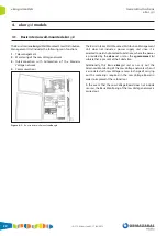
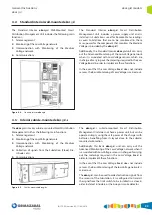
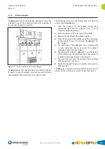
6.2.2. Cubicle-mounted
Once the ekor.gid-s unit has been installed on the
corresponding cubicle (the one closest to the Low Voltage
board being recommended), the general connections are
made, which are essential for telereading of the Low Voltage
meters. These connections are the following:
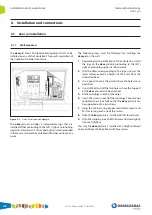
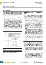
1. 4 voltage outputs (3P+N) of the Low Voltage board
to be monitored (and, therefore, for each Medium/
Low Voltage transformer available in the Substation).
This cable comes from the Low Voltage board and is
introduced through the packing gland at the back
of the cabinet, and connects wire-by-wire to the
double-level voltage terminals in the ekor.gid-s unit;
connecting to the bottom level of the terminal, which
has been purposely left without any connections, is
recommended.
2. 6 current outputs (Ia1-Ia2, Ib1-Ib2, Ic1-Ic2) of each Low
Voltage board to be monitored (and, therefore, for
each Medium/Low Voltage transformer available in the
Substation). This wiring comes from the Low Voltage
board and is fed through the packing gland located in
the lower part of the cabinet, to the disconnectable and
short-circuitable terminals of the ekor.gid-s unit.
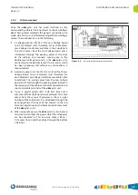
3. Up to 4 digital signals (ED1, Ed2, Ed3, Ed4 and 2
common) of the Substation to be monitored. This cable
comes from the sensors themselves or from a signal
hub box of the Substation. It is introduced through the
packing gland at the back of the cabinet, to the red
terminals (digital inputs) and black terminals (common)
of the ekor.gid-s unit.
4. When using safe power, the ekor.gid-s has two backup
terminals to distribute the power which the safe power
can be connected to. This twin-wire cable (+48 V
DC
/
0 V) comes from inside the cabinet through the bottom
side input.
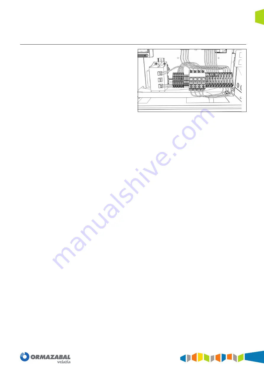
Figure 6.4.
Low Voltage Compartment connections
Summary of Contents for velatia ekor.gid
Page 31: ......


