


IG-175-EN version 02; 17/06/2016
8
Applications
General Instructions
ekor.gid
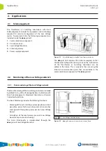
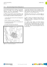
2.3. Monitoring of the Medium Voltage network
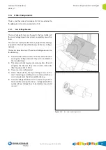
The Monitored Transformer or Switching Substations
include the equipment and technology required for
carrying out the remote reading of meters as well as the
Monitoring of the Medium Voltage network. To accomplish
this, the Transformer or Switching Substation will include
the following components:
Equipment for the monitoring of the Medium Voltage
network installed in the Medium Voltage switchgear of the
Transformer or Switching Substation.
An ekor.gid unit which includes:
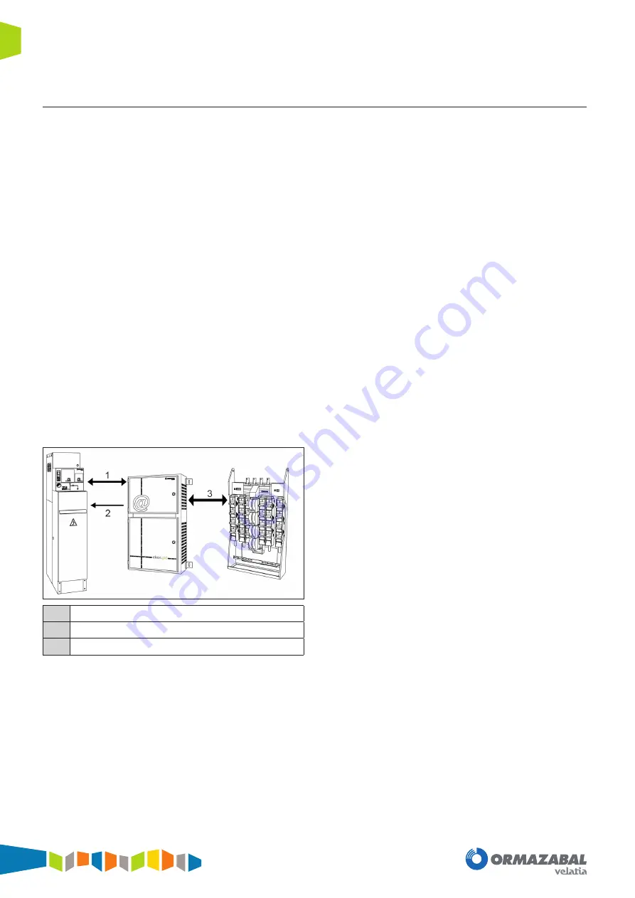
1. Communication components
2. PLC concentrator
3. Low Voltage network monitor(s)
4. Ethernet gateway
5. Power supply equipment: this power supply equipment
is also responsible for powering the equipment for
Monitoring the Medium Voltage network.
In cases where the Substation is monitored, in addition to
having an ekor.gid unit, there is at least one cubicle with an
ekor.rci unit, whose primary purpose is the Monitoring of
the Medium Voltage network.
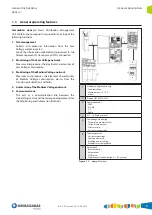
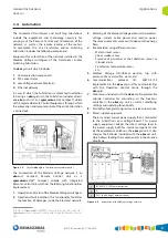
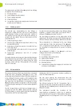
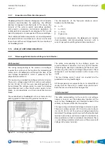
1
IEC 60870-5-104 Communications
2
V
DC
3
PLC - Low Voltage Communications
Figure 2.4. ekor.gid
communication with the Medium Voltage
switchgear
Monitoring of the Medium Voltage network corresponds to
the ekor.rci Integrated Control unit, which has the following
functions implemented:
• Directional fault indication.
This functionality facilitates the location of failures
inside the Electrical network.
• Metering of the Medium Voltage electrical parameters:
voltage, current, active power and reactive power. These
meterings are meant to optimise the energy flows.
• Detection of substation alarms coming from different
sensors:
- Water or level sensor
- Fire or smoke sensor
- Presence of personnel at the Substation sensor or
intruder alarm
- Transformer temperature sensor
- Others…
• Communications protocol IEC 60870-5-104 for
communicating with the Operation dispatching Centre
through communication components of the ekor.gid
unit.
• Web server included with the Integrated Control unit for
consulting all the functions available in the ekor.rci unit
as well as modifying settings and updating functionality.
Summary of Contents for velatia ekor.gid
Page 31: ......


