background image

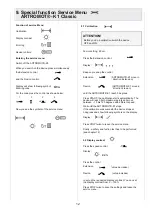
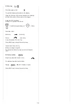
8.3 Error log

Press the symbol error log
You will find following information on the display:

Upper line: Number of the current showed error mes-
sage and the total number of the saved error messages.

Lower line: Error message
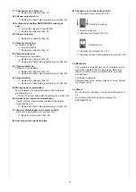
Left side: The symbol of the causer.

= Hand held programming unit

         = Motor

Press + or - to see the entries of the error log.
Press STOP twice to leave the service menu.

General note to the error log:

Entries are always in english.
The entries are ordered by causer and not in temporal
order.

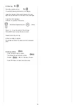
8.4 Device runtime

Press the symbol device runtime

.

The display shows the device runtime
Display:  


XX

(XX = Runtime in hours).

Press STOP twice to leave the service menu.

11

Summary of Contents for ATRTOMOT-K1

Page 1: ...Service Manual ARTROMOT K1...

Page 2: ...for the hand held program ming unit have to be closed at all times When you assembling with electronic parts make sure to use ESD Electro Static Discharge equipment Only original chip cards may be us...

Page 3: ...ld programming unit Pos 20 3 21 Range exceeded The measured angle is out of the range of motion Replace motor control Pos 25 22 ROM error in the hand held programming unit Memory error in the hand hel...

Page 4: ...held programming unit Use the correct hand held programming unit Pos 20 46 Handset error internal communication Invalid interchip communication inside the hand held programming unit Replace the hand h...

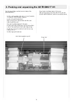
Page 5: ...iginal packaging for transport Put the hand held programming unit into the specified cutout of the styrofoam and fix it with adhesive tape Set the femur lenght on maximum and the lower leg setting on...

Page 6: ...ts ARTROMOT K1 Display Control logic Motor driver Micro processor Motor Control Hand held programming unit Microprocessor Control logic Pot Control Motor Pot Power supply 24 V DV Optional card reader...

Page 7: ...10 Belt loop 2 0013 087 11 Footrest complete with plate clamping lever belt 2 0037 032 Footrest 2 0013 300 Footplate 2 0037 168 Oval plate 2 0013 298 12 Fixation screw GN534 40 M6sw Rubber puffer comp...

Page 8: ...trol 2 0037 901RevB 26 Motor 0 0037 010 27 Wire set 2 0037 005 28 Power supply electronics 0 0034 244 29 Lip 2 0037 105 Wire for lip 0 0031 300 30 Spindel complete 0 0037 203 Power cord EU version 0 0...

Page 9: ...9 27 26 24 25 29 28 Position 30...

Page 10: ...tion starts automatically The device will reach both maximum points and move between 10 bis 120 degrees with different speed Wait until the ARTROMOT K1 stops If the calibration was succesful the devic...

Page 11: ...The symbol of the causer Hand held programming unit Motor Press or to see the entries of the error log Press STOP twice to leave the service menu General note to the error log Entries are always in en...

Page 12: ...ion ARTROMOT K1 move in direction Extension Flexion ARTROMOT K1 move in direction Flexion until the ARTROMOT K1 reach 0 degrees Press START the calibration starts automatically The device will reach b...

Page 13: ...and held programming unit Motor Press the control Extension last entry Flexion next entry to see the entries of the error log Press STOP twice to leave the service menu General note to the error log E...

Page 14: ...make sure to use ESD Electro Static Discharge equipment Remove the housing cover see chapter 10 1 Pull out the connectors of the motor control Loosen the four screws Exchange the defective motor cont...

Page 15: ...degrees Tolerance 5 degrees Check the angle in position 100 degrees Tolerance 5 degrees 3 Check the emergency off function Start the ARTROMOT K1 in any mode Press any key the ARTROMOT K1 will stop im...

Page 16: ...ion 0 degrees Tolerance 5 degrees Check the angle in position 60 degrees Tolerance 5 degrees Check the angle in position 100 degrees Tolerance 5 degrees 3 Check the emergency off function Start the AR...

Page 17: ...DIN EN 13485 ORMED Nr 018 829 01 ORMED GmbH Co KG Merzhauser Stra e 112 D 79100 Freiburg Tel 49 761 4566 01 Fax 49 0761 4566 5501 www ormed de E Mail info ormed de...

Reviews: