background image


Oznaczenia dźwiękowe i świetlne 


Status działania 

Czerwona dioda LED 

Zielona dioda LED 

Dźwięk 

Czytnik 

włączony 

świeci 

krótki pojedynczy dźwięk beep 

Czuwanie 

świeci 

Naciśnięcie klawiatury 

świeci 

krótki pojedynczy dźwięk beep 

Wejście w tryb programowania 

włączona 

krótki pojedynczy dźwięk beep 

Praca w trybie programowania 

miga 

miga 1 raz 

krótki pojedynczy dźwięk beep 

Poprawne wykonanie działania 

świeci 

miga 1 raz 

krótki pojedynczy dźwięk beep 

Błąd 

krótki pojedynczy dźwięk beep 

Wyjście z trybu programowania 

świeci 

krótkie 3 dźwięki beep 

Programowanie 

włączona 

krótki pojedynczy dźwięk beep 

Zwolnienie drzwi 

świeci 

1 dźwięk beep 

Wejście w tryb alarmu 

miga 

alarm 

Alarm 

miga 

wielokrotny dźwięk beep 

Naciśnięcie * / wprowadzenie kodu 
głównego 

miga 

krótki pojedynczy dźwięk beep 


Deklaracja zgodności: 

Orno-

Logistic Sp. z o.o. oświadcza, że typ urządzenia radiowego: OR-ZS-820, zamek szyfrowy z czytnikiem kart i breloków zbliżeniowych jest zgodny z dyrektywą 

2014/53/UE. Pełen tekst deklaracji zgodności UE jest dostępny pod następującym adresem internetowym: www.orno.pl 


(EN) User manual 

DESCRIPTION


A standalone  code lock which combines functions  of a  digital keypad,  as  well as cards  and proximity tags  reader.  It  is compatible  with  electromagnetic locks with 
access control systems. It has one relay output card and proximity tags reader that work at 125kHz frequency. This code lock is released with the use of cards and 
PIN codes. It can support up to 1000 PIN code users. Moreover, it has a visitor access function which allows to grant temporary access codes to 10 visitors. This 
code lock has been equipped with a backlit keypad and is suitable for surface mounting. Its working mode is indicated with a LED diode. 


PACKAGE LIST


After opening the packaging of the product, please make sure the product is intact and confirm the accessories are complete as per the list below: 


Keypad 

– 1 pc.  


Self-tapping screws 3x25mm. 


Screwdriver 

– 1 pc. 


Wall anchors 


IN4004 diode (for relay circuit protection) 

– 1 pc.


TECHNICAL SPECIFICATION


Power source:


9-18VDC


Current:


50mA (idle mode), 80mA (work mode) 

Ingress protection:


IP20


Number of users:   

1000 (990 standard users + 10 visitors) 

Dimensions: 

123x50x23mm 

Weight:


110g


Case material: 

ABS 

Surface color: 

anthracite 

Operation range: 

ca. 3-6cm 

Operating temperature: 

-

40°C ~ 60°C 

Operating humidity: 

10%RH ~ 90%RH 


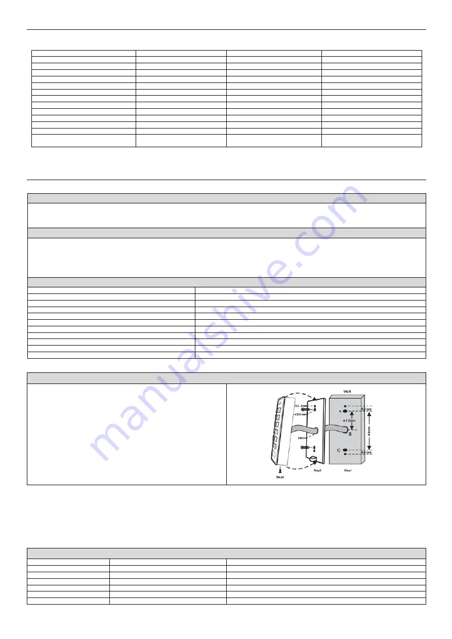
INSTALLATION 


1. 

Remove the back cover from the unit. 

2. 

Drill 2 holes (A, C) on the wall for the screws and one for the cable. 

3. 

Knock the supplied wall anchors to the screw holes (A, C).  

4. 

Fix the back cover firmly on the wall with 4 flat head screws. 

5. 

Put the cable through the cable hole (B). 

6. 

Attach the unit to the back cover. 


WIRES 


Color: 

Function: 

Notes: 

orange 

NC 

Normally closed relay output 

purple 

COM 

Common connection for relay output 

blue 

NO 

Normally open relay output 

black 

GND 

Grounding 

red 

9-18V 

9-18VDC regulated power input 

yellow 

EXIT 

Exit button (connected to GND) 

Summary of Contents for OR-ZS-820

Page 1: ...z tytułu obecności w sprzęcie niebezpiecznych substancji mieszanin oraz części składowych Z drugiej strony zużyty sprzęt to cenny materiał z którego możemy odzyskać surowce takie jak miedź cyna szkło żalazo i inne Symbol przekreślonego kosza na śmieci umieszczany na sprzęcie opakowaniu lub dokumentach do niego dołączonych wskazuje na konieczność selektywnego zbierania zużytego sprzętu elektryczneg...

Page 2: ...krywą PRZEWODY Kolor przewodu Funkcja Uwagi pomarańczowy NC Styk normalnie zamknięty przekaźnika fioletowy COM Styk wspólny przekaźnika niebieski NO Styk normalnie otwarty przekaźnika czarny GND Masa czerwony 9 18V Regulowane zasilanie czytnika żółty WYJŚCIE Przycisk wyjścia dalej do GND SCHEMAT POŁĄCZENIA Zasilanie standardowe Uwaga zalecamy zastosować diodę 1N4004 lub inną podobną diodę w celu z...

Page 3: ...yjściu po aktywacji urządzenia Etap programowania Kombinacja klawiszy 1 Wejście w tryb programowania kod główny 2 Tryb monostabilny czasowy LUB Tryb bistabilny przerzutnikowy 4 1 99 Czas przekaźnika wynosi od 1 do 99 sekund 1 to 50mS Czas ustawiony fabrycznie to 5 sekund 4 0 Włączenie lub wyłączenie trybu bistabilnego 3 Wyjście z trybu programowania Konfiguracja czasu alarmu Zastosuj poniższe krok...

Page 4: ... do karty to 1234 numer ID użytkownika stary numer PIN nowy numer PIN nowy numer PIN Kasowanie użytkownika używając jego numeru ID Użycie numeru ID spowoduje skasowanie wszystkich przypisanych do niego kart i numerów PIN Etap programowania Kombinacja klawiszy 1 Wejście w tryb programowania kod główny 2 Kasownie użytkownika za pomocą numeru ID 2 ID użytkownika 3 Wyjście z trybu programowania Wprowa...

Page 5: ...rk at 125kHz frequency This code lock is released with the use of cards and PIN codes It can support up to 1000 PIN code users Moreover it has a visitor access function which allows to grant temporary access codes to 10 visitors This code lock has been equipped with a backlit keypad and is suitable for surface mounting Its working mode is indicated with a LED diode PACKAGE LIST After opening the p...

Page 6: ...ved PROGRAMMING 1 Keypad configuration Set master code The 6 digits master code is used to prevent unauthorized access to the system To interface with the keypad the administrator will need a master code factory default code 123456 It is highly recommended to immediately update and record your master code when you use the device for the first time Programming step Keystroke combination 1 Enter pro...

Page 7: ...from 0 989 3 Exit programming mode Delete user cards Programming step Keystroke combination 1 Enter programming mode Master code 2 Delete card by card reading OR Delete card select specific user s ID 2 Read card Repeat step 2 for additional user cards 2 User ID The user ID is any number from 0 989 3 Exit programming mode Add or delete a PIN Programming step Keystroke combination 1 Enter programmin...

Page 8: ...mode engaged flashing alarm Alarm flashing beeps Pressing toggles standby master code entry flashing Short single beep Declaration of conformity Orno Logistic Sp z o o declares that the product OR ZS 820 Code lock with cards and proximity tags reader is compatible with Directive 2014 53 EU The full text of the EU declaration of conformity is available at the following Internet address www orno pl ...

Page 9: ...ID Nummer PIN Code Die ID Nummer ist eine beliebige Zahl aus dem Bereich 0 989 Die PIN Nummer ist eine beliebige Folge von 4 6 Ziffern aus dem Bereich 0000 999999 ausgenommen ist die Kombination 1234 Löschen der Benutzerkarte 2 Registerkarte 2 ID Nummer Verlassen des Programmiermodus Wie Sie Zugang erhalten Kartenbesitzer Bewegen Sie die Karte näher an das Lesegerät Benutzer mit PIN Nummer Geben S...

Page 10: ...ch dem Lesen der richtigen Karte PIN oder der Eingabe des Mastercodes freigegeben wird Durch Drücken der Eingabetaste wird die Tür geöffnet wenn sich die Tastatur im gesperrten Modus befindet Phase der Programmierung Tastenkombination 1 Eintritt in den Programmiermodus Master Code 2 Sperre AUS ODER Sperre EIN ODER Sperre EIN Alarm 6 0 Standard Einstellung 6 1 Zugangssperre für 10 Minuten 6 2 Aktiv...

Page 11: ...rte 2 Benutzer ID 3 Verlassen des Programmiermodus Wichtig Die Anzahl der Eingänge wird durch den Bereich 0 9 bestimmt wobei 0 10 mal Benutzer Gast ID Nummer ist eine beliebige Kombination von Ziffern aus dem Bereich 990 999 Die PIN Benutzer Gästekartennummer muss eindeutig sein und sich von den Standard PIN und Kartennummern unterscheiden ANDERE Zurücksetzen auf die Werkseinstellungen 1 Schalten ...

Reviews: