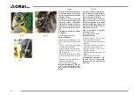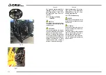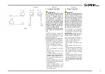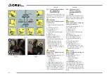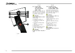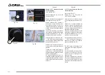
Fig. 76
1
2
Fig. 77
10
9
11
Fig. 78
12
13
14
Fig. 79
5.8.3 Comandi servo
proporzionali SERVO
TRONIC
(mod. Acrobaat 5.5, Acrobat 5.5 LH, Acrobat 6.6, Acrobat
6.6 LH, Acrobat 6.5 T Acrobat 6.5 T LH Acrobat 7.6 T,
Acrobat 7.6 T LH, Acrobat 509, Acrobat 509 LH, Acrobat
609, Acrobat 609 LH, Acrobat Visual, Acrobat 609 Visual,
Acrobat 555 Ventral, Acrobat 555 Ventral LH, Leader GP
509, Leader GP 659, Leader GP 589 Ventral, Leader GP
679 Ventral, Leader GP 710 Ventral, Leader GP 779 T,
Leader GP 815 T, Power 600, President 600 Visual, Pre-
sident 600 Visual Telescopic)
ATTENZIONE
Invertire il senso di rotazione solamen
-
te a rotore fermo.
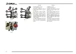
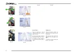
1) Sospensione oleopneumatica (“Fig. 76”);
2) Rotazione (“Fig. 76”);
3) Movimento attrezzo terminale (“Fig. 76”);
4) Non presente (“Fig. 76”);
5) Movimento telescopico (“Fig. 76”);
6) Flottante (“Fig. 76”);
7) Rotazione oraria (“Fig. 76”);
8) Rotazione antioraria (“Fig. 76”);
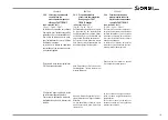
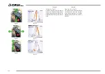
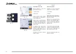
9) Chiave d’accensione (“Fig. 78”);
10) Pulsante avvio rotore: abbinato ai
pulsanti (7 o 8, “Fig. 76”). I pulsanti (7
e 8, “Fig. 76”) si escludono a vicenda.
ATTENZIONE
Attendere 30” prima di riaccendere il
rotore.
11) Fungo d’emergenza (“Fig. 78”);
12) Display (“Fig. 78”):
- Allarme temperatura olio;
- Totale ore;
- Parziale ore.
13) Joystick (“Fig. 78”);
14) Pulsante azzeramenti ore (“Fig. 78”);
A) e B) Movimento primo braccio (“Fig. 76”);
C) e D) Movimento secondo braccio (“Fig. 76”).
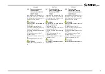
Collegare il filo marrone (1, “Fig. 77”) al
polo positivo e il filo blu (2, “Fig. 77” al polo
negativo della batteria.
5.8.3
Servo proportional controls
SERVO TRONIC
(mod. Acrobaat 5.5, Acrobat 5.5 LH, Acrobat 6.6, Acro-
bat 6.6 LH, Acrobat 6.5 T Acrobat 6.5 T LH Acrobat 7.6
T, Acrobat 7.6 T LH, Acrobat 509, Acrobat 509 LH, Acro-
bat 609, Acrobat 609 LH, Acrobat Visual, Acrobat 609
Visual, Acrobat 555 Ventral, Acrobat 555 Ventral LH, Le-
ader GP 509, Leader GP 659, Leader GP 589 Ventral,
Leader GP 679 Ventral, Leader GP 710 Ventral, Leader
GP 779 T, Leader GP 815 T, Power 600, President 600
Visual, President 600 Visual Telescopic)
ATTENTION
Reverse the direction of rotation only
when rotor is stationary.
1) Oleopnumatic suspension (“Fig. 76”);
2) Rotation (“Fig. 76”);
3) Movement terminal tool (“Fig. 76”);
4) Missing (“Fig. 76”);
5) Telescopic movement (“Fig. 76”);
6) Floating (“Fig. 76”);
7) Clockwise rotation (“Fig. 76”);
8) Anticlockwise rotation (“Fig. 76”);
9) Ignition key(“Fig. 78”);
10) Engine start button: coupled to the
buttons (7 or 8, “Fig. 76”). The buttons
(7 and 8, “Fig. 76”) mutually exclude
themselves.
ATTENTION
Wait 30 minutes efore turning on the
rotor again.
11) Emergency stop (“Fig. 78”);
12) Display (“Fig. 78”):
- Oil temperature alarm;
- Total hours;
- Partial hours.
13) Joystick (“Fig. 78”);
14) Reset button hours (“Fig. 78”);
A) and B) Moving first arm (“Fig. 76”);
C) and D) Second arm movement (“Fig. 76”).
Connect the brown wire (1, “Fig. 77”) to
the positive pole and the blue wire (2, “Fig.
77”) to the negative pole of the battery.
140
ITALIANO
ENGLISH
Summary of Contents for Acrobat 4.4
Page 5: ...River Compact 355 River Compact 420 Royal 550 Royal 660 Royal 650 T Royal 760 T Vigna 615 T 5...
Page 45: ...45 DEUTSCH ESPA OL FRAN AIS ITALIANO ENGLISH...
Page 57: ...57 DEUTSCH ESPA OL FRAN AIS ITALIANO ENGLISH...
Page 227: ...227...
Page 256: ...256...
Page 257: ...257...

