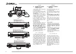
4.2 COLLEGAMENTO ATTREZZI
TERMINALI SU MACCHINE
ORSI GROUP SRL
4.2.1 Collegamento testata
trinciante
AVVERTENZA
Assicurarsi del perfetto serraggio delle
viti prima di sollevare l’accessorio.
Se l’attrezzo terminale è corredato di
rotore con mazze da taglio, il senso di
rotazione del rotore deve essere obbli
-
gatoriamente ORARIO, dal lato motore
(guida destra). Se la guida è a sinistra
si inverte il verso di rotazione.
In caso di serbatoio in pressione, la
pressione non deve essere superiore a
quella sopportabile dalla guarnizione di
tenuta rotante sull’albero motore.
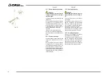
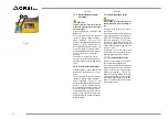
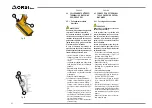
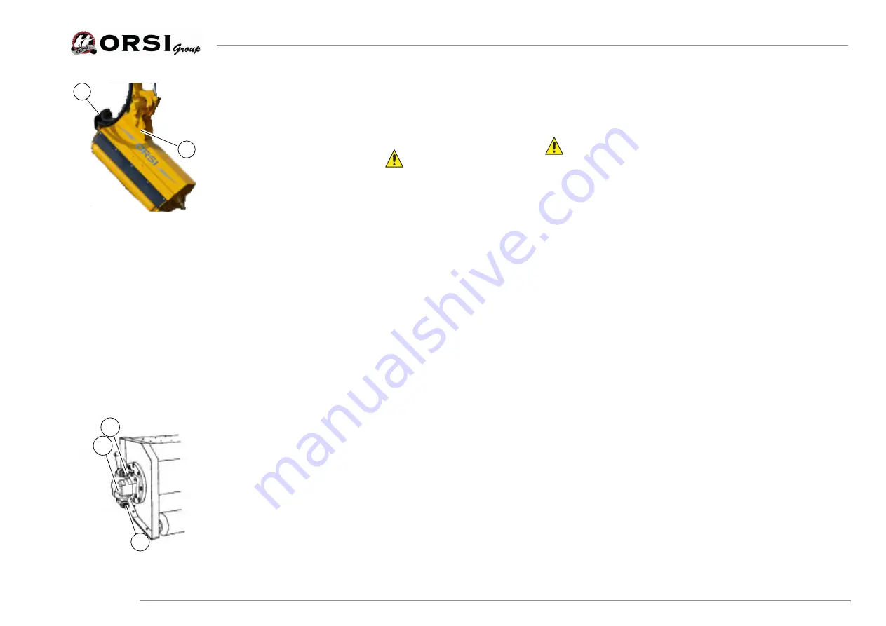
• Fissare la testata al braccio articolato
utilizzando quattro dei fori già esistenti
(1, “Fig. 27”) sul telaio della testata trin-
ciante.
• La piastra di collegamento viene fornita
dalla ditta Orsi Group srl su richiesta
specifica.
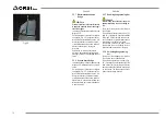
• Smontare il carte di protezione (2).
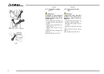
• Collegare i tubi di mandata e ritorno olio
sul raccordo (3 o 4), in quanto il motore
è reversibile.
• Collegare il tubo di drenaggio.
Se l’impianto non è corredato di distributore:
• Collegare il tubo di mandata sul raccordo (4)
per ottenere il senso di rotazione “ORARIO”.
• Collegare il tubo di mandata sul raccordo (4)
per ottenere il senso di rotazione “ANTIORA-
RIO”.
• Collegare il tubo di ritorno olio sul raccordo (3).
• Collegare il drenaggio (5) (in caso il motore ne
sia corredato)con il tubo direttamente al serba-
toio senza attraversamento di filtri, radiatori e
ogni altro elemento interposto.
• Assicurarsi che non vi siano contropressioni
all’interno del tubo.
3
4
5
Fig. 28
4.2 CONNECTION OF TERMINAL
TOOLS ON ORSI GROUP SRL
MACHINES
4.2.1
Carving head connection
PRUDENCE
Make sureof the tightness of the bolts
before lifting accessory.
If the terminal tool is provided with
rotor with hammers, the sense of rota
-
tion of the rotor must be compulsorily
clockwise, from the motor side (right
guide). If you drive on the left invert the
sense of rotation.
In case of the pressure tank, the pres
-
sure must not be higher than the one
bearable by the seal which rotates seal
on the motor shaft.
• Fix the head to the articulated arm using
four of the existing holes (1, "Fig 27") on
the frame of the cutting head.
• The connecting plate is supplied by com-
pany Orsi Group Ltd. on specific request.
• Remove the cover (2).
• Connect the out and input oil pipes on
the fitting (3 or 4), because the motor is
reversible.
• Connect the drainage pipe.
If the system is not equipped with distributor:
• Connect the output pipe on the joint (4)
to obatin "CLOCKWISE" rotation.
• Connect the output oil pipe on the joint
(4) to obtain the "ANTICLOCK WISE"
rotation.
•
Connect the oil return pipe on the fitting (3).
• Connect the drain (5) (in case the engine
is equipped with it) with the pipe directly
to the tank without passing through fil
-
ters, radiators and any other interposed
element.
• Make sure that there are no back pres-
sure within the pipe.
1
22
Fig. 27
82
ITALIANO
ENGLISH
Summary of Contents for Acrobat 4.4
Page 5: ...River Compact 355 River Compact 420 Royal 550 Royal 660 Royal 650 T Royal 760 T Vigna 615 T 5...
Page 45: ...45 DEUTSCH ESPA OL FRAN AIS ITALIANO ENGLISH...
Page 57: ...57 DEUTSCH ESPA OL FRAN AIS ITALIANO ENGLISH...
Page 227: ...227...
Page 256: ...256...
Page 257: ...257...

