8
receiving instrument. Since the input impedance of
the receiving instrument is normally 1000Ω or
more,theeffectiveinstrumentinputimpedancewith
the 100Ω terminator will be of the order of 93Ω and
this matches the cable impedance correctly.
For series termination use the 93Ω output of the
572A for the cable connection. Use 93Ω cable to
interconnect this into the input of the receiving
instrument. The 1000Ω (or more) normal input
impedance at the input connector represents an
essentially open circuit, and the series impedance
in the 572A now provides theproper termination for
the cable.
For the combination of series and shunt
termination,usethe93Ωoutputon therearpanelof
the 572A and use 93Ω cable. At the input for the
receiving instrument use a BNC tee to attach both
the signal cable and a 100Ω resistive terminator.
Note that the signal span at the receiving end of
this type of circuit will always be reduced to 50% of
the signal span furnished by the sending
instrument.
For customer convenience, ORTEC stocks the
proper terminators and BNC tees, or they can be
ordered from a variety of commercial sources.
3.7. SHORTING OR OVERLOADING THE
AMPLIFIER OUTPUTS
All outputs of the 572A are dc-coupled with an
output impedance of about 0.1Ω for the front panel
connectors and 93Ω for the rear panel connectors.
If the output is shorted with a direct short circuit the
output stage will limit the peak current of the output
so that the amplifier will not be harmed. When the
amplifier is terminated with 100Ω, the maximum
rate allowed to maintain the linear output is
[200000 cps/τ(µs)] x [10/V
o
,(V)].
3.8. INHIBIT OUTPUT CONNECTION
The Inhibit output on the rear panel is intended for
application at the anticoincidence input of the
Analyzer. An output pulse is generated through this
connector when a pulse pileup is sensed in the
572A, and the pulse can then be used to prevent
the Analyzer from measuring and storing a false
amplitude. The signal is dc-coupled and rises from
0 to about +5 V for a time equal to 6τ, starting when
a pileup occurs.
3.9. BUSY OUTPUT CONNECTION
The signal through the rear panel Busy output
connector rises from 0 to about +5 V at the onset of
each linear input Pulse. Its width is equal to the
time the input pulse amplitude exceeds the BLR
discriminator level, and is extended automatically
by the generation of an Inhibit output signal. It can
be used to provide MCA live-time correction, to
control the generation of input pulses, to observe
normal operation with an oscilloscope, or for any of
a variety of other applications. Its use is optional
and no termination is required if the output is not
being used.
3.10. CRM OUTPUT CONNECTION
OneNIM-standardpositivelogicpulseisgenerated
to correspond to each linear input pulse into the
572A. The pulses are available through the CRM
(Count Rate Meter) output BNC on the rear panel
and are intended for use in a count rate meter or
counter to monitor the true input count rate into the
amplifier. Its use is optional and no termination is
required if the output is not being used.
4. OPERATING INSTRUCTIONS
4.1. INITIAL TESTING AND
OBSERVATION OF PULSE WAVEFORMS
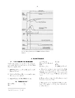
Refer to Section 6 for information on testing
performance and observing waveforms at front
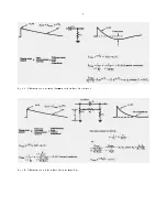
panel test points. Figure 4.1 shows some typical
unipolar and bipolar output waveforms.
4.2. FRONT PANEL CONTROLS
GAIN
A coarse Gain switch and a Gain 10-turn
lockingprecisionpotentiometerselectandprecisely
adjust the gain factor for the amplification in the
572A. Switch settings are X20, 50, 100, 200, 500,
and 1000. Continuous fine gain range is from X0.5
to X1.5, using markings of 500 through 1500 dial
divisions. An internal jumper setting provides one
additional gain factor selection of either X1.0 or
X0.1. Collectively the range of gain can be set at
Summary of Contents for 572A
Page 6: ...vi...


