10
this connector is about 0.1 Ω. Linear range of 0 to
±10V.
4.4. REAR PANEL CONNECTORS
IN
Bridged with front panel input connector for
optional use as an alternate input connection
location.
INH
Provides an output signal to identify a pulse
pileup in the 572A. Connect it to the
anticoincidence input of the multichannel analyzer
to inhibit measurement and storage of false
amplitudes.
UNI
Provides a unipolar positive output with the
same characteristics as described for the front
panelUniconnector;theoutputimpedancethrough
this connector is 93Ω.
BI
Provides a bipolar output with the same
characteristics as described for the front panel BI
connector; the output impedance through this
connector is 93Ω.
CRM
Provides a NIM-standard (
....
+5 V) slow
positive logicoutputforeachlinearinputpulse. The
output can be connected into a ratemeter or
counter to monitor the true input count rate for the
amplifier.
BUSY
Providesasignalthatrisestoapproximately
+5V for the time that the input pulse amplitude
exceeds the BLR discriminator level, which can be
controlled manually or automatically. The output
can be used to correct for live time in the ORTEC
MCA by connecting it to the MCA Busy input.
PREAMP
Providespowerconnectionsfromthebin
and power supply to the ORTEC preamplifier. The
dc levels i24 V, -24 V, +12 V, and -12 V.
4.5. STANDARD SETUP PROCEDURE
a.
Connect the detector, preamplifier, high voltage
powersupply,andamplifierintoabasicsystemand
connect the amplifier unipolar output to an
oscilloscope.Connectthepreamplifierpowercable
tothePreamppowerconnectoron the rear panelof
the 572A. Turn on power in the Bin and Power
Supply and allow the electronics of the system to
warm up and stabilize.
b.
Set the 572A controls initially as follows:
Shaping
2 µs
Coarse Gain
50
Gain
1.000
Internal Jumper
X1.0
BLR
PZ Adj
Thresh
Fully clockwise
Pos/Neg
Match preamplifier
output polarity
c.
Use a
60
Co calibration source, set about 25 cm
from the active face of the detector. The unipolar
output pulse from the 572A should be about 8 to
10 V, using a preamplifier with a conversion gain of
170 mV/MeV.
d.
Readjustthe Gain control so that thehigherpeak
from the
60
Co source (1.33 MeV) provides an
amplifier output at about 9 V.
4.6. POLE-ZERO ADJUSTMENT
The pole-zero adjustment is extremely critical for
good performance at high count rates. This
adjustmentshouldbecheckedcarefullyforthebest
possible results.
USING Ge(Li) SYSTEM AND
60
Co
a.
Adjust the radiation source count rate between
2 kHz and 10 kHz.
b.
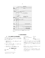
Observe the unipolar output with an
oscilloscope. Adjust the PZ Adj control so that the
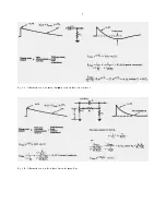
trailing edge of the pulses returns to the baseline
without overshoot or undershoot (see Fig. 4.2).
The oscilloscope used must be dc-coupled and
must not contribute distortion in the observed
waveforms. Oscilloscopes such as Tektronix 453,
454, 465, and 475 will overload for a 10-V signal
when the vertical sensitivity is less than 100
mV/cm. To prevent overloading the oscilloscope,
use the clamp circuit shown in Fig. 4.3.
USING SQUARE WAVE THROUGH
PREAMPLIFIER TEST INPUT
A more precise pole-zero adjustment in the 572A
can be obtained by using a square wave signal as
the input to the preamplifier. Many oscilloscopes
include a calibration output on the front panel and
this is a good source of square wave signals at a
frequency of about 1 kHz. The amplifier
differentiates the signal from the preamplifier so
Summary of Contents for 572A
Page 6: ...vi...


