14
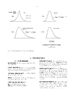
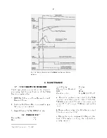
Fig. 4.7. Noise as a Function of Bias Voltage.
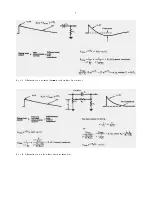
Fig. 4.8. System for Measuring Resolution with a Pulse
Height Analyzer.
N
(
FWHM
)
'
2.35
E
rms
E
dial
E
o
(
N
det
)
2
%
(
N
amp
)
2
'
(
N
total
)
2
where E
dial
is the pulser dial reading in MeV and
2.35 is the factor for rms to FWHM. For average-
respondingvoltmeterssuchastheHewlett-Packard
400D, the measured noise must be multiplied by
1.13 to calculate the rms noise.
The resolution spread will depend on the total input
capacitance, since the capacitance degrades the
signal-to-noise ratio much faster than the noise.
D E T E C T O R N O I S E - R E S O L U T I O N
MEASUREMENTS
The measurement just
described can be made with a biased detector
insteadoftheexternalcapacitorthatwouldbeused
to simulate detector capacitance. The resolution
spread will be larger because the detector
contributesbothnoiseandcapacitancetotheinput.
The detector noise-resolution spread can be
isolated from the amplifier noise spread if the
detector capacity is known, since:
where N
total
is the total resolution spread and N
amp
is
the amplifier resolution spread when the detector is
replaced by its equivalent capacitance.
The detector noise tends to increase with bias
voltage, but the detector capacitance decreases,
thus reducing the resolution spread. The overall
resolution spread will depend upon which effect is
dominant.Figure4.7showscurvesof typicalnoise-
resolution spread versus bias voltage, using data
from several ORTEC silicon surface-barrier
semiconductor radiation detectors.
A M P L I F I E R N O I S E - R E S O L U T I O N
MEASUREMENTS USING MCA
Probably the
most convenient method of making resolution
measurements is with a pulse height analyzer as
shown by the setup illustrated in Fig. 4.8.
The amplifier noise-resolution spread can be
measured directly with a pulse height analyzer and
the mercury pulser as follows:
a.
Select the energy of interest with an ORTEC 419
Precision Pulse Generator. Set the amplifier gain
so that the energy is in a convenient channel of the
analyzer.
b.
Calibrate the analyzer in keV per channel, using
the pulser; full scale on the pulser dial is 10 MeV
when calibrated as described above.
c.
Obtain the amplifier noise-resolution spread by
measuring the FWHM of the pulser peak in the
spectrum.
The detector noise-resolution spread for a given
detector bias can be determined in the same
mannerbyconnectingadetectortothepreamplifier
input. The amplifier noise-resolution spread must
be subtracted as described in "Detector Noise-
Resolution Measurements." The detector noise will
vary with detector size and bias conditions and
possibly with ambient conditions.
Summary of Contents for 572A
Page 6: ...vi...

