UNIT
BLACK (BLK)
SENSOR
SWITCH
SWITCH BOX
POWER SUPPLY
120V AC
GROUND (GRD)
BROWN (BRN)
WHITE (WHT)
FAN
RECEPTACLE
SENSOR
RECEPTACLE
FAN
SWITCH
FAN
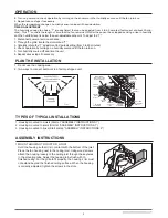
Run 120 V AC house wiring to the location of the fan. Use only UL-approved connectors (not included) to attach the house wiring to the
wiring plate. Refer to the wiring diagram, and connect the wires as shown.
ASSEMBLY INSTRUCTIONS
CONNECT ELECTRICAL WIRING
3
2. MOUNT WITH HANGER BARS
Insret the hanger bars into the slots in the housing. Place the fan
housing between the joists, make sure the bottom of the housing
is even with the finished ceiling. Extend the hanger hars to the
joist. Use screws to secure the hanger bars to the
ceiling joists.
DUCT
3. ATTACH DAMPER/DUCT CONNECTOR
Snap the damper/duct connector onto the fan housing. The
connector must be flush with the top of the housing, and the
damper flap should fall closed.
4. INSTALL ROUND DUCTWOTK
Connect the round ductwork (not included) to the damper/duct connector,
and run the ductwork to a roof or wall cap (not included). Using tape (not
included), secure all the ductwork connections so that they are air tight.
D
For OD-5006HS OD-8011HS
For OD-5006 OD-8011
UNIT
BLACK (BLK)
SWITCH BOX
FAN
SWITCH
POWER SUPPLY
120V AC
GROUND (GRD)
WHITE (WHT)
WIRE
PANEL
WIRE
PANEL
FAN
RECEPTACLE
FAN


