CONNECTION OF CONTROLS
Ventilators
MODEL
ODD-ERV-80 | ODD-ERV-120
Instruction Manual
1-888-543-6473
1-888-541-6474
13376 Comber Way
Surrey BC V3W 5V9
info@ortechindustries.com
www.ortechindustries.com
375 Admiral Blvd
Missis
s
auga
,
ON L5T 2N1
Speed Setting
The control system enables equal speed settings or synchronous
speed correcting for the supply and extract fan. (see
ALL
)
If the air resistance differential in the supply and extract air ducts
the speed of the supply and extract fan can be individually adjusted
and this setting will be saved in the controller memory (see
SPL
and
Eht
, respectively).
The controller circuit board has a digital indicator and <KEY1>,
<KEY2>, <KEY3> buttons which are used for operation mode setup
and editing of the operation parameters. After switching on power,
the ventilation unit operates normally and the light indicator is off.
Press <KEY1> to open the setup menu. Select the required menu
item using the buttons <KEY2> and <KEY3>. The display shows the
current setting of the menu item.
OPERATION MODES
<
Eht
>: set air flow for the active speed in the extract air duct in
CFM in the range from 40 CFM up to 120 CFM. For instance, in case
of activated HIGH speed, the changes establish new air flow in the
extract air duct. The new value will be a set air flow value for the
HIGH speed in the extract air duct. To display or change the value,
turn on the required speed (<LOW>, <MEDIUM> or <HIGH>), press
the <KEY1> button and set the required value for the air flow in
the extract air duct using the <KEY2> and <KEY3> buttons. Press
the <KEY1> button to save the value in the non-volatile memory
and return to the setup menu.
<
ALL
>: set air flow for the active speed both in the supply and
extract air ducts in CFM in the range from 40CFM up to 120CFM.
The set air flow is displayed according to the previous air flow
settings in the supply air duct for the active speed. For instance, in
case of activated LOW speed, the changes establish new air flow
both in the supply and extract air ducts synchronously. The new
value will be a set air flow value for the LOW speed in the supply
and extract air duct. To display or change the value, turn on the
required speed (<LOW>, <MEDIUM> or <HIGH>), press the <KEY1>
button and set the required value for the air flow in the supply and
extract air ducts using the <KEY2> and <KEY3> buttons. Press the
<KEY1> button to save the value in the non-volatile memory and
return to the setup menu.
<
SPL
>: set air flow for the active speed in the supply air duct in CFM in the range from 40CFM up to 120 CFM. For instance, in case of activated
MEDIUM speed, the changes establish new air flow in the supply air duct. The new value will be a set air flow value for the MEDIUM speed in
the supply air duct. To display or change the value, turn on the required speed (<LOW>, <MEDIUM> or <HIGH>), press the <KEY1> button and
set the required value for the air flow in the supply air duct using the <KEY2> and <KEY3> buttons. Press the <KEY1> button to save the value in
the non-volatile memory and return to the setup menu.
<
dEF
>:
reset to the factory settings (default settings). To reset to
the factory settings, press <KEY1>, then select <-Y-> using the
<KEY2> and <KEY3> buttons and press the <KEY1> button. To edit
the factory settings, select the <-n-> value using the <KEY2> and
<KEY3> buttons and press the <KEY1> button. The ventilation unit
revers to the manual settings.
<
Cor
>: Temperature corrections. To correct the temperature value
communicated by the temperature sensor, press the <KEY1>
button, change the temperature set point using the <KEY2> and
<KEY3> buttons, then press the <KEY1> button.
<
Prg
> software version. Press the <KEY1> button to display it.
In case of alarm, the alarm message <Err> is displayed. To detect
the alarm root, press the <KEY1> button and review the list of all
alarm messages using the <KEY2> and <KEY3> buttons. The alarm
message consists of a number (1, 2, 3) and a letter (n, Y). The
number determines the alarm message type.
1.
Fire alarm activation
2.
Temperature sensor short circuit
3.
Temperature sensor breakout
The letter indicates no alarm (n) or available alarm (Y).
Examples:
•
<1-Y>: fire alarm activation. If the fire alarm panel is
disconnected, it means that the controller contacts 31 and 32
are not jumpered.
•
<2-Y>: temperature sensor short circuit
•
<3-n>: no temperature sensor breakout
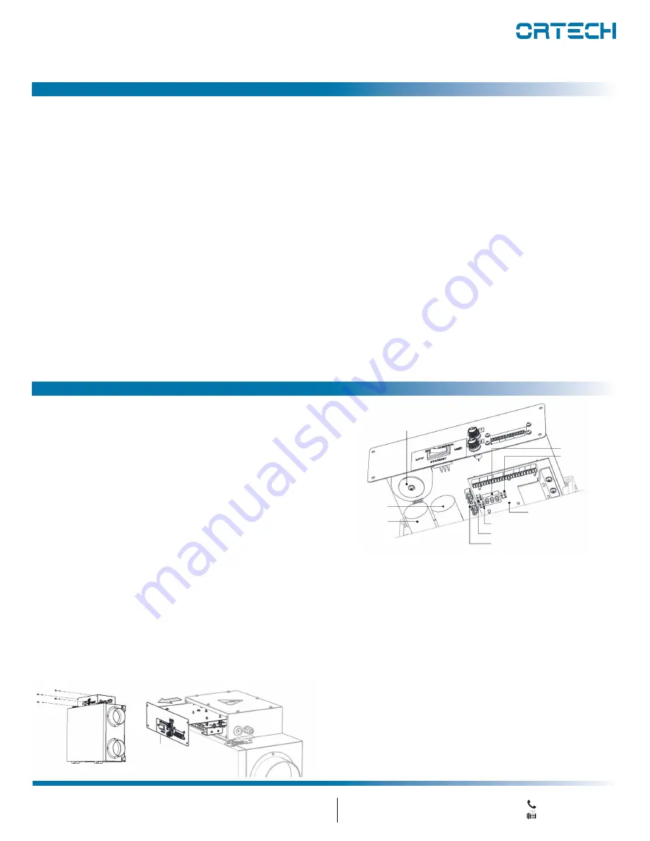
Access to the control circuit board and location of the indicator
and control buttons.
TR1 power transformer
C2 capacitor
C1 capacitor
HL1 light indicator
KEY1 button
Controller
KEY2 button
KEY3 button
X2 earth terminal block


