65
64
7.8 Wheel change
A wheel/tyre change requires technical
knowledge. You should therefore have
this work carried out by an authorised
workshop. Sitting in the wheelchair dur-
ing a wheel change is not permitted.
The wheelchair must stand on a level
and firm surface. Before starting the dis-
assembly work, support the frame to
prevent the wheelchair from tipping
over and secure it to prevent an unwant-
ed movement or tipping over.
Always change tyres in pairs because
differently worn tyres can impair the
straight-on travel of the wheelchair.
7.8.1 Disassembling the drive
wheels
Tool:
Phillips screwdriver
13 mm socket spanner
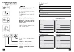
Screw out the screws of the hub cap and
remove the hub cap.
Then screw out the five inner wheel se-
curing screws (Fig. 87/
➀
) take off the
wheel and fully deflate the tyre.
7.8.1.1 Tyre change
Tool:
13 mm socket spanner
!
Attention:
The screws secured with red caps on
the outer wheel rim (Fig. 87/
➁
) hold
together the rim halves and must not
be screwed undone until the tyre is
fully deflated.
To change the tyre, fully deflate the tyre,
then remove the red caps and screw out
the screws (Fig. 94/
➀
). Now separate
the rim halves.
☞
Note:
– The valve points to the outside dur-
ing the assembly.
– Press the red caps (Fig. 87/
➁
) on
again after the rim halves have been
assembled.
87
85
86
1
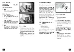
7.7.4 Rear light
Festoon bulb:
24V/C5W S8.5
Tool: Phillips screwdriver
☞
Note:
Use a dry cloth to hold the glass body
of the new filament bulb.
7.7.4.1 Removal:
– Switch off the control unit.
– Pull out the security plug and the
main fuse.
– Undo the securing screws and screw
off the lens (Fig. 85).
– Press the defective festoon bulb
against the holding pin (Fig. 85/
➀
)
and then pull it out of the holder.
☞
Note:
The armrest (incl. the lighting unit)
can be detached for a festoon bulb
replacement (see 'Armrest' section).
7.7.4.2 Fitting:
– Insert the new festoon bulb. - Press
one tip into the hole in the holding
pin and then press the other tip into
the hole of the other holding pin (Fig.
85/
➀
).
– Mount the lens. - Press in the lens
and fasten it with the securing screws
(Fig. 86).


