background image

Assembly Manual

Summary of Contents for Laser Master 2 PRO S2

Page 1: ...Assembly Manual...

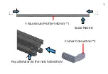
Page 2: ...Y Aluminum Pro le 540mm 1 Corner Connectors 2 Scale Mark 0 Pay attention to the notch direction 1...

Page 3: ...Scale Mark 0 Scale Mark 0 X Aluminum Pro le 460mm 2 M5 25mm Screws 2 2...

Page 4: ...M5 Pro le Nuts 4 Tighten with a 2 5mm Hexagon Wrench 3...

Page 5: ...Scale Mark 0 Corner Connectors 2 Pay attention to the notch direction Y Aluminum Pro le 540mm 1 4...

Page 6: ...Tighten with a 2 5mm Hexagon Wrench M5 25mm Screws 2 5...

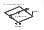
Page 7: ...Put X axis assembly onto the frame X axis Assembly 1 Scale Mark 0 Scale Mark 0 6...

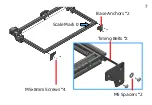
Page 8: ...Base Anchors 2 M5 8mm Screws 4 M5 Spacers 2 Timing Belts 2 Scale Mark 0 7...

Page 9: ...The timing belt needs to pass through the wheels 8...

Page 10: ...M5 Pro le Nuts 2 Mainboard Assembly 1 Y Limit Switch 1 The timing belt must be tightened and then locked with screw M5 8mm Screws 4 9...

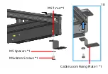
Page 11: ...M5 8mm Screws 1 Cable Loom Fixing Plate 1 1 M5 Spacers 1 M5 T nut 1 10...

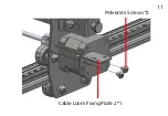
Page 12: ...M4 6mm Screws 2 Cable Loom Fixing Plate 2 1 11...

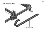
Page 13: ...Install Cable Loom Cable Loom 1 12...

Page 14: ...M4 6mm Screws 2 Cable Tie 1 13...

Page 15: ...M4 6mm Screws 2 Cable Tie 1 Ground Wire The wire terminal must be inserted into the end of the port Black Red 14...

Page 16: ...Laser Wire Y connect to Y axis motor L connect laser wire X connect X Cable Ties 2 Black Red Ground Wire 15...

Page 17: ...X connect to X axis motor M5 8mm Screws 2 LU2 4 SF haven t this Focal Gauge Holder but a Focal Gauge Board Focal Gauge Gauge Holder 1 Cable Tie 1 M5 T nut 2 16...

Page 18: ...Screws 2 Ground Wire 3Pin Nuts 2 Laser Wire Cable Ties 2 Thumb Screw 1 17 LU2 2 LU2 4 LF Laser Module...

Page 19: ...Thumb Screw 1 3Pin Laser Wire Cable Ties 2 Ground Wire 18 LU2 4 SF Laser Module...

Reviews: