background image


13 


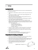
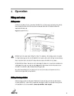
Connect the power cord to the SCA and then to a suitable grounded receptacle. 

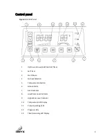
Power on the SCA using the main power ON/OFF switch located at the rear of the unit. 

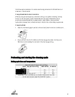
Press one of the four temperature preset buttons or the Heat Off button to select the 
cleaning temperature. The temperature can be changed at any time during the cycle by 
selecting a different temperature button. The SCA heats at a rate of about 3 minutes per 
degree.  

Press the SET button and then press the up and down arrows to set the minutes. Press 
the SET button again and use the up and down arrows to set the hours. Press the SET 
button again to accept the time. Press the 

 button to start the heater and pump. 


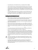
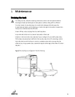
Loading parts and testing level sensors 

Wait until the SCA has reached the desired temperature before loading parts into the 
tank. This minimizes the time the parts are immersed in the cleaning solution. 

To load parts for cleaning, place parts inside the large cleaning basket. If cleaning small 
parts, place the parts inside the small basket and set the small basket inside the large 
basket. Close the basket lids. 

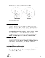
Before placing the basket into the cleaning solution, press the 

 button to pause the 

heater and pump. With the basket cutout facing the nozzle, slowly lower the large parts 
basket into the solution-filled tank. The flow nozzle should be centered on the basket 
cutout. 

If the high level alert lights and the alarm sounds, press the 

 button to silence the 

alarm, and remove liquid until the alert indicator is no longer lit. 

Note: It is recommended that the level sensors be tested periodically. Adding water to 
just above the MAX fill line should cause the high level alert to illuminate and the buzzer 
to sound. Draining water until the liquid level is below the MIN fill line should cause the 
low level alert to illuminate and the buzzer to sound. If the level sensors are properly 
working the system will not operate until the liquid level is between the MIN and MAX 
fill lines. 

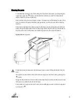
Close the lids on the SCA to prevent heat loss and evaporation. Never place your face 
near the tank when opening the lid 

 vapors from the cleaning solution may cause eye 

and respiratory irritation. 

Fermez les couvercles de 

SCA afin d’éviter la perte de chaleur et l’é

vaporation. Ne 

jamais placer votre visage près du réservoir lorsque vous ouvrez le couvercle ; les 

vapeurs s’émanant de la solution de nettoyage


pourraient causer de l’irritation des yeux 

et des voies respiratoires. 


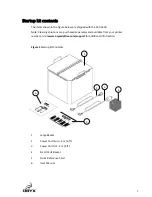
Summary of Contents for sca3600

Page 1: ......

Page 2: ...2 This page intentionally left blank...

Page 3: ...aining and disposal 10 Operation 11 Filling and setup 11 Preheating and starting the cleaning cycle 12 Completing the cleaning process 15 Maintenance 16 Draining the tank 16 Disposing of solution 17 C...

Page 4: ...require the unit to be plugged into a Ground Fault Interrupt GFI or similar protected outlet Always power off and unplug the SCA from the power outlet when it is being cleaned moved or serviced Do not...

Page 5: ...tout autre fin que de retirer les mat riaux de support solubles de pi ces 3D imprim es Portez des gants thermiques et des lunettes de s curit lorsque vous travaillez avec ou proximit du SCA Reportez...

Page 6: ...l in a bath consisting of water or cleaning solution The SCA is designed to accommodate a broad range of material specific cleaning solutions and bath temperatures The gentle bath agitation dissolves...

Page 7: ...lutions are purchased separately and available from your printer reseller or visit www oryxadditive com support for additional information Figure 1 Startup Kit Contents 1 Large Basket 2 Power Cord Eur...

Page 8: ...ponents 1 Large Parts Basket 2 Drain Strainer 3 Control Panel 4 Cleaning Tank 5 On Off Switch and Power Cord Receptacle 6 Drain Valve 7 Flow Nozzle 8 Pump Intake Screen 6 5 7 1 2 3 4 Figure 2 Major Co...

Page 9: ...tart Pause 4 No heat Selection 5 Temperature Selection 6 Silence Alarm 7 Alert Indicator 8 Low Water Level Indicator 9 High Water Level Indicator 10 Temperature LED Display 11 Pump Operating LEDs 12 P...

Page 10: ...0320 C19 right angle o Cord H05VV F jacket rating 15A 250V o Conductors 1 5mm2 x 3 The power cord plug in receptacle is a disconnecting device that should be easily accessible at all times Position th...

Page 11: ...ank unless the liquid level is above the MIN line as shown N UTILISEZ PAS d eau chaude lors du remplissage du r servoir L ajout de concentr s de nettoyage l eau est une r action de d gagement de chale...

Page 12: ...s SDS for PPE and handling requirements If using EcoWorks 1 Open the foil cleaning agent packet as shown Each packet contains an A B pouch 2 Empty all the contents of 13 thirteen foil cleaning agent...

Page 13: ...to the cleaning solution press the button to pause the heater and pump With the basket cutout facing the nozzle slowly lower the large parts basket into the solution filled tank The flow nozzle should...

Page 14: ...ing cycle by opening the SCA lids and slowly lifting the large basket from the cleaning solution Rest the front of the basket on the inner tank rim and the lower rear basket lugs pins on the support b...

Page 15: ...des pi ces mouill es avant qu elles n aient t rinc es Let the basket rest above the tank while draining After draining remove the parts from the basket and rinse them with water to remove any residua...

Page 16: ...ue vous travaillez avec les effluents Power off the unit and unplug from the wall receptacle Ensure the drain strainer is in place at the bottom of the tank Attach a 1 inch 25 4 mm inner diameter hose...

Page 17: ...using EcoWorks a dilution of 1 part clean water to 1 part used solution is usually sufficient More dilution may be required please check your local regulations Cleaning the SCA Apply mild soap and wat...

Page 18: ...gged with debris This will noticeably reduce the flow in the tank Remove the intake screen by pulling down with sufficient force to unseat the fastening clips from the mating surface Scrub debris from...

Page 19: ...es What to Do Power Indicator is not Lit after pressing the button Power switch is not On Press rocker switch on the back of the unit to the On position Power cord is not connected to unit or wall Che...

Page 20: ...lids and lift the part basket from the tank Let the liquid cool and try starting the cycle again If it overheats a second time contact technical support Over temperature sensor has tripped A resettabl...

Page 21: ...t Pump intake screen is clogged Drain the tank as instructed in the Maintenance section Clean the intake screen with a stiff brush until debris is removed from the holes Flow from nozzle is not unifor...

Page 22: ...Works is a more efficient cleaning concentrate Liquid Level indicators did not turn off when liquid was added removed from the tank Sensors or Indicators have failed Contact technical support System i...

Page 23: ...n Power specifications Source nominal 230VAC 10 50 60 Hz 15A 3400W Facility specifications Installation location Level floor able to support 204 kg 450 lbs Power requirements A grounded electrical out...

Page 24: ...sed Otherwise to receive technical support www oryxadditive support proceed to the Request Technical Support page and fill out the support request form send an e mail to support oryxadditive com Pleas...

Page 25: ...accident improper installation improper maintenance or improper operation or application or if the machine was improperly repaired or serviced by the customer This warranty is void if the system is n...

Reviews: