12
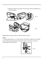
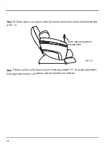
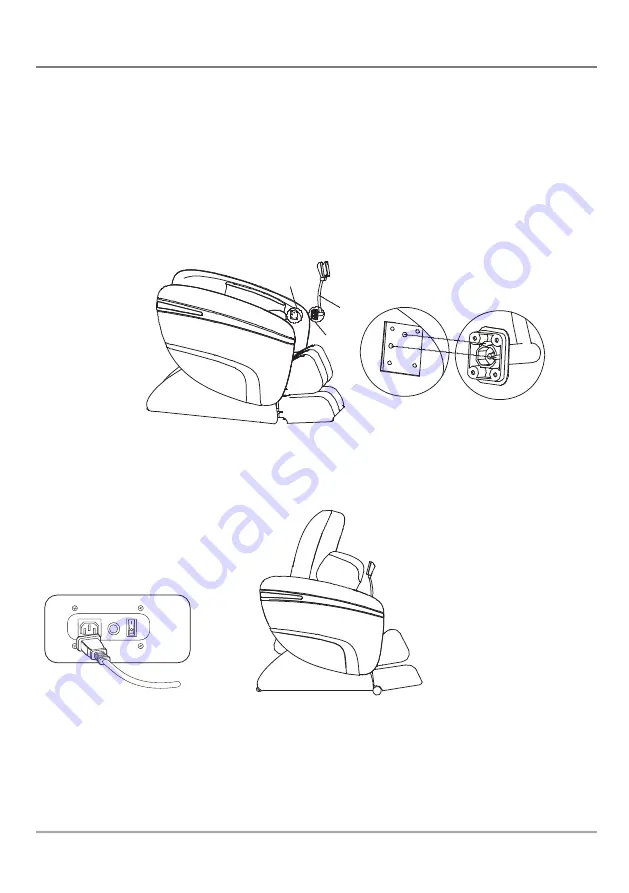
Step 12:
Connect the wire plugs.
PIC 12
Step 11:
Install the controller.
Adjust the positioning holes of controller to match with the ones in the side panel as
demonstrated in PIC 11. Lock the screws which are with flat pad when holes C’, D’, E’, F’
are corresponding to hole C, D, E, F.
Note:
1. The A and B in PIC 11 are corresponding to PIC 10’s A and B.
2. The screws and the gaskets used in this step are packed in a small bag marked “3”.
PIC 10
PIC 11
A
A
C
C'
D
D'
E
E'
F
F'
7
B
B
Summary of Contents for OS-7200H Pinnacle
Page 1: ...User Manual OS7200H...
Page 32: ......


