background image

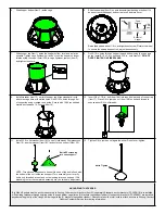
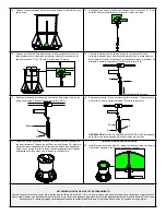
13.  Place completed assembly into feeder hopper. Align cone support onto 

axle assembly.

14. 

Ensure feed flow control (Item 14) is set to ‘0’. Remove bottom two (2) 

nuts and spring and set aside.

15. 

Place feed flow control onto crossbar with back side of assembly resting 

against flat side of crossbar. Install the feed flow control to crossbar with 

5/16 x 7/8-in. bolt and 5/16-in. flange nut.

16. 

Connect feed flow control and cone strap. Hold cone strap upwards 

against nut on feed flow control (A), and adjust nut (A) until cone is lightly 

resting on feed sweep. Tighten second nut (B) against nut (A).

17. 

Slide feed flow control spring onto bolt from the bottom up. Thread nuts 

(C & D) behind it.

18.  While holding a wrench on nut (A), tighten nut (C) to tension the spring to 

a length of 3.5-in. Tighten nut (D) against nut (C). 


NOTE: Refer to ADJUSTMENT RECOMMENDATIONS below to set the 

recommended cone height to start pigs.

19.  Place bump bar agitators (Items 21) into the two middle holes on the 

crossbar. Install washer and nuts (Items 22). Adjust length of bump bars 

with the nut. Use pliers to hold the bump bars in place. When the wheel 

is turned, the bump bars should only drag along the hopper bottom about 

one-fourth of a full circle.

OPTIONAL LID INSTALLATION

20. 

Install fiberglass hopper lid (Item 24) by aligning indentions in lid with 

crossbar. Attach hook and spring to crossbar to secure.

ADJUSTMENT AND TRAINING RECOMMENDATIONS

To train pigs on the feeder, set feed flow control to 1 1/2 to 2 and manually turn feed wheel until feed begins to flow into trough. Manually scoop feed into the 

trough and fill for first use. As first trough full is eaten, pigs learn through play that the feed wheel dispenses feed. Adjust the cone height with feed flow control 

as needed. Proper adjustment will vary based upon feed grind, moisture content and animal size.

H

H

T

T

H

H

L

L

N

N

M

O

H

H

Hold cone strap up

A

B

R

R

SECTION R-R

D

C

Spring

P

P

SECTION P-P

A

3.5 in.

C

D

H

H

T

T

Summary of Contents for Big Wheel RN1 Series

Page 1: ...Item 10 into center recess of trough Item 12 Drill 3 16 in holes through trough using axle as guide Secure using 10 24 flat head machine screws and 10 24 nuts Items 11 13 2 Place 3 4 in feed wheel washer Item 9 on axle followed by feed wheel Item 8 If wheel does not turn freely check for and remove paint or galvanizing residue 3 Force trough divider cage Item 6 onto trough using rubber mallet Ensu...

Page 2: ...Item 17 Place 3 8 in jam hex nut Item 18B on bolt and thread to expose about 3 4 in of threads 11 Install 5 16 in flat washer Item 18C on bolt followed by fiberglass cone Item 19 another washer Item 18C and onto cone support Item 20 NOTE Thread cone support onto bolt until the end of the bolt is flush with the bottom of the nut inside cone support Turn assembly over to verify bolt is only threaded...

Page 3: ...recommended cone height to start pigs 19 Place bump bar agitators Items 21 into the two middle holes on the crossbar Install washer and nuts Items 22 Adjust length of bump bars with the nut Use pliers to hold the bump bars in place When the wheel is turned the bump bars should only drag along the hopper bottom about one fourth of a full circle OPTIONAL LID INSTALLATION 20 Install fiberglass hopper...

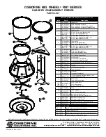
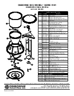
Page 4: ...embly stainless steel 11 IN BOLT KIT 10 24 flat head machine screws 4 ea 12 KF N10003 Trough 13 IN BOLT KIT 10 24 flange nuts 4 ea 14 KF F10024 Feed flow control 15 KF N10011 or KF N1ZP04 Crossbar Crossbar zinc plated 16 IN BOLT KIT 10 24 round head machine screws 4 ea 10 24 crossbar nuts 4 ea 17 KF N10013 or KF N1ZP05 Cone strap Cone strap zinc plated 18A 18B 18C INCLUDED IN BOLT KIT 3 8 x 1 1 2 ...

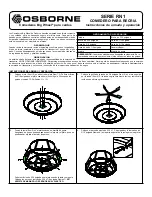
Page 5: ...nsabilidad de la empresa de transporte NO DE OSBORNE INDUSTRIES Para proteger sus derechos en caso de daño o pérdida firme la guía de despacho sólo después que la empresa de transporte haya reconocido el daño o la pérdida por escrito En caso que el daño se conozca sólo al terminar de desempacar informe inmediatamente a la empresa de transporte y solicite una inspección de la mercancía dañada antes...

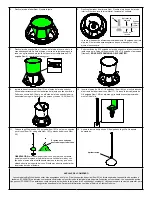
Page 6: ...la barra del cono Ítem 17 Coloque la tuerca fijadora de 3 8 pulgada Ítem 18B en el perno y gire hasta exponer aproximada mente 3 4 del hilo 11 Coloque la golilla plana de 5 16 pulgada Ítem 18C en el perno seguida por el cono Ítem 19 otra golilla Ítem 18C y el soporte del cono Ítem 20 OBSERVACIÓN atornille el soporte del cono en el perno de manera que el perno sólo ingrese al final de la tuerca Vol...

Page 7: ...S DE AJUSTE más abajo para fijar el alto recomendado del cono al iniciar a los cerdos 19 Ubique las barras agitadoras Ítem 21 en los dos orificios centrales de la barra transversal Coloque las golillas y tuercas Ítemes 22 Ajuste la altura de las barras agitadoras con las tuercas Sujete las barras agita doras con un alicate Al girar la rueda las barras agitadoras sólo deben arrastrarse por más o me...

Page 8: ...10 24 4 c u Tuercas barra transversal 10 24 4 c u 17 RFN 0811 Barra del cono Barra del cono de zinc 18A 18B 18C RFB 3200 RFN 3500 RFW 2000 Perno 3 8 x 1 1 2 pulg Tuerca aseg hex 3 8 pulg Golilla de soporte del cono 5 16 pulg 2 c u 19 KF F10004 Cono 20 KF F10009 Soporte del cono Soporte del cono de zinc 21 FF 00RF1B ó FF 00RF1ZP Barra agitadora 2 c u Barra agitadora de zinc 2 c u 22 RFN 2400 RFW 20...

Reviews: