
19
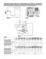
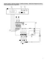
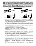
6 - Electric connection
Important: installation should be made following the manufacturer's instructions, by qualified personnel only, in conformity
with the electric safety regulations in force. Please refer to the electrical diagram at page 7.
At the input of the supply it is necessary to install an omni-polar magnetothermic/differential device with contact opening
equal to 3 mm and adequate cutoff power.
Caution:
Before connecting the cabinet to the power mains make sure the supply voltage corresponds to the rating on
the serial number plate (consider that the maximum voltage variations admissible are +/- 10%). Make sure the electric
connection is made with cables of a diameter and length capable of withstanding the power and current absorbed by the
display cabinet (TAB. 2 page 4). Cabinets with incorporated compressor are supplied with a cable and plug 2,5 mt long
(FIG. 14 page 4) therefore, it is essential not to exceed this measure in connecting the cabinet to the wall socket. The
cable should be fully extended in a safe position away from possible impact and at a distance from liquids or water and
heat sources. In case of breakage of the power cable of the cabinet, it must be replaced by the manufacturer or by
institution in charge of it. The plug should be accessible even after installation of the cabinet.
Important:
installation should be made following the manufacturer's instructions, by qualified personnel in conformity with
the electric safety regulations in force in the country where the cabinet is installed (electric safety regulations and laws,
accident prevention laws, fire prevention regulations, directives).
Always ground the cabinet.
The manufacturer is not liable for any injuries caused by failure to respect this regulation.
If there is no wall socket near where the cabinet is to be installed, provide for connection in conformity with the regulations
in force.
Do not use adapter plugs.
The manufacturer has no liability for any damage to personnel or property caused by improper installation.
7 - Technical features
The cabinet is supplied with a plastic bag containing this manual of instructions that must be kept. It contains technical
data, wiring diagrams and tables concerning the cabinet.
The technical data are also shown on the rating plate (FIG. 15 page 4). It indicates:
1. Name and address of the manufacturer
2. Commercial name of the cabinet
3. Cabinet code
4. Cabinet serial number
5. Rating
6. Frequency
7. Max absorbed current
8. Max absorbed power
9. Max absorbed power during defrosting
10. Standard lighting power
11. Net display area
12. Type of cooling gas used
13. Weight of cooling gas loaded in each unit
14. Climate class and reference temperature (dry bulb)
15. Electrical safety factor
16. Work schedule number
17. Work order number
18. Year of manufacture
19. Heating capacity
20. QR code
21. EAC marking
Important:
The rating plate and warning labels should never be removed. The manufacturer is not liable for any damages
caused by failure to respect this regulation.
This is to certify that the product complies with Legislative Decree no. 108 of 25/01/1992 applying EEC Directive 89/109
concerning materials and objects expected to come into contact with food products.
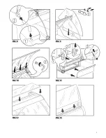
8 - Filling with products and use of the cabinet (startup)
With the cabinet off, remove the plastic film protection on the inside and outside and clean the cabinet according to the
instructions in paragraph 11.
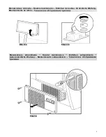
After correctly assembling the cabinet (Par. 5) plug it into the mains (as described in Par. 6) and switch the cabinet on,
switch the light on using the switches on the control panel on the rear (FIG. 16 page 4). The gentle hum of the motor and
illumination of the display will indicate that the cabinet is working. The display (FIG. 16 page 4) on the rear casing shows
the working temperature of the display case. The instruction manual for the electronic control to which the display refers is
enclosed with the instruction booklet (tampering with this device is impossible because a password is required and only a
specialized expert can intervene on it). The thermostat and gas charge are set in the factory. Tampering with the factory
settings relieves the manufacturer of any liability.
About three hours after switching the cabinet on, you can start filling it with products. Always check that the temperature
reading on the display of the electronic control is suitable for the conservation of the products placed in the display
cabinet.