LMW-170 SERIES LCD MONITOR User Manual
—
26
—
Sub Menu
Settings
Explanation
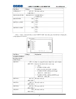
USER CONFIG 5/5
-NEXT PAGE
-UMD PROTOCAL
LOCAL
LOCAL/TSL3.1/TSL4.0/IMAGE VIDEO
y
LOCAL:
Use UMD setting (USER CONFIG
2/5) to control the UMD.
y
TSL3.1:
Use the TSLV3.1 protocol setting to
control the UMD from a TSL tally controller.
y
TSL4.0:
Use the TSLV4.0 protocol setting to
control the UMD from a TSL tally controller.
y
IMAGE VIDEO:
Use the Image video
protocol setting to control the UMD from an
Image Video tally controller (TSL-1510).
-UMD ID
0
0 – 255
The UMD ID will determine which DISPLAY will
be show.
-UMD NAME(S/N)
M00000
16 Characters for Option
y
Use this setting to assign a name to the
Remote Display.
y
Press ENTER to edit the UMD name.
y
Use UP and DOWN to select characters.
y
Press ENTER to go to next cursor. Press
MENU to exit editor.
-BAUD RATE
19200
9600/19200/38400
-LED TLY
OFF
ON/OFF
Set the LED Tally ON or OFF.
-OSD TLY MODE
OFF
RG/GR/RGY/OFF
Use this setting to choose OSD Tally Mode.
Only the TALLY SOURCE is STANDARD or
SIV422 can make the setting be
available.
-UMD TLY MODE
T1
T1/T2/T1T2/T2T1/T1-/T2-/T1T2-/T2T1-
Use this setting when using the Image Video tally
control. This setting will determine the state which
is selected.
-TLY SOURCE
STANDARD
STANDARD/IMAGE VIDEO HW/IMAGE VIDEO
422/SIV422//TSL
y
STANDARD:
Use the Standard setting to
control tally via contact closure on GPI tally.
y
IMAGE VIDEO HW:
Use the Image Video
HW setting to control Image Video tally states via
contact closure on the GPI tally interface. Contact
closure of the Red pin corresponds to the left
Tally, and the Green pin maps to right Tally.
Contact closure (ground) corresponds to a LOW
state, and open circuit corresponds to a HIGH

