background image


LMW-230 SERIES LCD MONITOR           User Manual


- 16 - 

Sub Menu 

Settings 

Explanation 

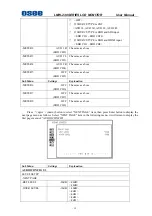
-MARKER LEVEL 

<1>

Sets the luminance to display safety, center and area 

marker line. 

y


<1>: 50% white level 

y


<2>: 75% white level   

y


<3>: 100% white level 

-MARKER MAT 

<OFF>

Sets the area marker mat transparency.   

y


<OFF> : Normal background, only use line for area 

marker edge indication 

y


<HALF> : 50% background brightness 

y


<BLACK> : Black   


™


16:9 and 4:3 area marker settings are stored separately.   

Use 16:9 setting if display aspect is 16:9; Use 4:3 setting if display aspect is 4:3 

™


Marker is disabled when SCAN is NATIVE, input is DVI or VGA. 

VIDEO CONFIG 


For the video inputs include SDI1, SDI2, Line1, Line2 or DVI-I (HDMI input only), the following 

items are displayed. 


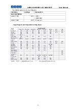
Sub Menu 

Settings 

Explanation 

VIDEO CONFIG   

PICTURE CONTROL 

-APERTURE 0

<0-100> 


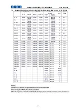
For the DVI/VGA input, the following items are displayed. 

Summary of Contents for LMW-230 Series

Page 1: ...LMW 230 SERIES LCD MONITOR USER MANUAL...

Page 2: ...0 2012 COMPANY NAME Beijing Osee Digital Technology Ltd CONTACT INFORMATION HEAD OFFICE Address Room 702 Tower D Jinyujiahua Building No 9 3rd Shangdi Street Haidian District Beijing China Post code 1...

Page 3: ...he images of LMW 230H are adopted in the following descriptions Any of the different specifications between the device types are elaborated Before reading the manual please confirm the device type Not...

Page 4: ...Signals and Adjustable setting Items 10 Chapter 5 Menu Operation Guide 11 5 1 Selecting the Menu Language 11 5 2 Using the Menu 12 Chapter 6 LMW 230 Series LCD Monitor Menu Structure 13 6 1 Main Menu...

Page 5: ...must accept any interference received including interference that may cause undesired operation Note This equipment has been tested and found to comply with the limits for a Class B digital device pur...

Page 6: ...ed is used to place the monitor on 2 Place the monitor on the soft surface screen face down for installation of table stand 3 Use the included screws to attach the table stand The table stand attaches...

Page 7: ...LMW 230 SERIES LCD MONITOR User Manual 3 Chapter 3 Dimensions Front View Unit mm Rear View Unit mm...

Page 8: ...LMW 230 SERIES LCD MONITOR User Manual 4 Side View Unit mm Top Side View Unit mm...

Page 9: ...rm or vector graph It is used to check the wave form or vector graph of the displaying signal picture Only used for SDI signal You can open and set the wave form or vector graph on the second page of...

Page 10: ...720P60 YES YES YES 1080I60 YES YES YES 1080I50 YES YES YES 1080P24 YES YES YES 1080P25 YES YES YES 1080P30 YES YES YES 1080P50 YES YES 1080P60 YES YES 1080SF24 YES YES YES VGA YES YES SVGA YES YES XGA...

Page 11: ...minance Y signal of Y C or YPbPr LINE2 C Pb LINE 2 Input Terminal Chroma C signal of Y C or Pb Blue component of YPbPr LINE2 Pr LINE 2 Input Terminal Pr Red component of YPbPr DVI I DVI D VGA HDMI DVI...

Page 12: ...GPI 1 GPI 6 see the fourth page of USER CONFIG menu CONFIG Configuration Terminal It is used to update the hardware program only RS485 IN RS485 IN Terminal It is used to support dynamic UMD Tally RS48...

Page 13: ...Menu Or make the Main Menu disappear when it is on DOWN F2 Following Three status No any Menu F3 Related to the menu page of user config 3 5 F2 BUTTON Main Menu Select the next Item on the Menu Volume...

Page 14: ...YES YES YES YES YES Phase NTCS Sharpness YES YES YES YES YES YES NTSC Setup NTSC Compo Level SMPTE 480I60 SMPTE SMPTE SMPTE SMPTE Color Temp YES YES YES YES YES YES YES YES SCAN YES YES YES YES YES Y...

Page 15: ...n The menu appears The menu presently selected is shown in yellow 3 Press up or down button to select the first page of USE CONFIG menu then press the ENTER button The setting items icons in the selec...

Page 16: ...lect Field Pressing Up down key can select the control item Pressing Enter key can enter into the sub adjustable item Pressing Menu key can return to main menu 3 Control Item Select Field Pressing Up...

Page 17: ...DEO CONFIG 1 AUDIO CONFIG 3 USER CONFIG 5 CONTROL 1 6 2 Adjusting and Changing the Settings STATUS The STATUS menu is used to display the current status of the unit The following items are displayed F...

Page 18: ...depending on the unit model COLOR TEMP The COLOR TEMP menu is used for adjusting the picture white balance Sub Menu Settings Explanation COLOR TEMP COLOR TEMP D65 Used to select the color temperature...

Page 19: ...Explanation MARKER MARKER ENABLE ON ON marker displayed OFF marker not displayed AREA MARKER 15 9 Selects the area marker aspect ratio according to the display aspect For display aspect ratio is 16 9...

Page 20: ...edge indication y HALF 50 background brightness y BLACK Black 16 9 and 4 3 area marker settings are stored separately Use 16 9 setting if display aspect is 16 9 Use 4 3 setting if display aspect is 4...

Page 21: ...signal SHIFT H 50 Adjusts the horizontal position of the picture 0 100 SHIFT V 50 Adjusts the vertical position of the picture 0 100 DOT PHASE 50 Adjusts the dot phase 0 100 1 For AUTO SETUP menu it...

Page 22: ...D CH16 If SOURCE TYPE is EBD and HDMI input EBD CH1 EBD CH2 Sub Menu Settings Explanation SPEAKER R AUD 1R EBD CH2 The same as above METER POSITION HORIZONTAL HORIZONTAL VERTICAL METER DISP OFF OFF ON...

Page 23: ...R 5 OFF EBD CH5 The same as above Sub Menu Settings Explanation METER 6 OFF EBD CH6 The same as above METER 7 OFF EBD CH7 The same as above METER 8 OFF EBD CH8 The same as above Press up or down butto...

Page 24: ...FF Sets the power saving mode turn on off PANEL include backlight and panel power supply signal to panel y ON the monitor goes into power saving mode if no signal is input for about one minute y OFF t...

Page 25: ...other signal 5 COLOR MATRIX is only applied to 480i 60 or 480 60p input signal and it will be set in blue color when other signal Press up or down button to select NEXT PAGE item then press Enter butt...

Page 26: ...next page menu as follows Sub Menu Settings Explanation USER CONFIG 3 4 FUNCTION BUTTON SETUP NEXT PAGE F1 BUTTON MARKER F1 F3 button functions can be set as follows y MARKER Control all MARKER ON OF...

Page 27: ...y NORMAL SCAN y OVER SCAN y NATIVE y ASPECT 4 3 y ASPECT 16 9 y MARKER ENABLE GPI2 TALLY G The same as above GPI3 SDI 1 The same as above GPI4 SDI 2 The same as above GPI5 LINE 1 The same as above GP...

Page 28: ...determine which DISPLAY will be show UMD NAME S N M00000 16 Characters for Option y Use this setting to assign a name to the Remote Display y Press ENTER to edit the UMD name y Use UP and DOWN to sel...

Page 29: ...tally setting are the same as STANDARD and IMAGE VIDEO 422 This mode requires to the UMD tally mode parameter to be set User can set the OSD tally level via 422 port y TSL Use the TSL 422 setting to c...

Page 30: ...ating Temperature 0 C to 50 C 7 2 Inputs HD SDI Inputs with Loop through 1 Video Input 1 Configurable Video Y C YPbPr Input 1 Configurable HDMI VGA DVI Input 4 Channels Audio Input GPI Inputs on RJ45...

Page 31: ...0X1080 1280x720 1280x720 1280x720 1920X1080 50 709 720P30 1216X684 1920X1080 1280x720 1280x720 1280x720 1920X1080 30 709 720P50 1216X684 1920X1080 1280x720 1280x720 1280x720 1920X1080 50 709 720P60 12...

Page 32: ...R User Manual 28 Chapter 8 Supplied Accessories Standard accessories 1 Display 1 2 AC Power Cord 1 3 M4 x 8mm Screws 7 4 Warranty Card 1 5 Table Stand 1 6 User Manual 1 Note Specifications are subject...

Reviews: