PC-30 Filter control unit operating manual Page: 14
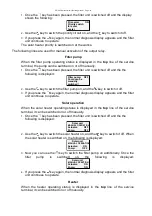
Filter pump run-on time
This line displays for how long the filter pump runs on after the additional heater
has been switched off. This value can be adjusted to meet the requirements of the
relevant filter unit if it is displayed in the
top
line:
1.
Once the key has been pressed, the filter unit is switched off and the display
shows the following:
Run-on: s
Filter pump run
on time after
add. heater
10
2.
Now use the and keys to change the warm-up time. The smallest
adjustable value is 0s, the largest 1800s
3.
If you press the key again, the normal diagnosis display appears and the filter
unit continues to operate. The adjusted value will be saved automatically.
Filter pump run-on is switched off at the works (run-on time = 0).
Pump operation time
This line displays the total operating hours for the filter pump.
Heater operating time
This line displays the total operating hours for the additional heater.
Solar operating time
This line displays the total operating hours for the solar heater.
Backflushing counter (internal)
This line displays how often a backflushing process has been started by bar
valves.
Backflushing counter (external)
This line displays how often a backflushing process has been started by the
EUROTRONIK-10.
The following lines enable the service technician to carry out an examination of the input
signals and filter control unit output relay.
Forced switch-on of NR-12-TRS-2
This line displays whether the NR-12-TRS-2 level regulation system is subject to
forced switch-on.
The following displays are possible:
Forced switch-on
OFF
No forced switch-on, or terminals 11 and 12 not connected.
Forced switch-on
ON
Forced switch-on requested, or terminals 11 and 12
connected.
EUROTRONIK-10 backflushing signal
This line displays whether the EUROTRONIK-10 switches the filter pump on during
backflushing or rinsing.
The following displays are possible:
EUROTRONIK OFF
no switch-on command from EUROTRONIK-10


