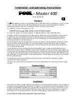
Installation and operating instructions
-
Master 400
Art.No.3002800130
Function:
The
Pool Master 400 filter control enables a 400V 3-phase filter pump to be switched on or off in a timed
manner. The time of day and the individual switching periods are set in accordance with the enclosed
operating instructions of the timer. The selection switch on the front cover is used to:
(a) Switch the function of the system on or off.
CAUTION: this does not isolate all poles of the control from supply!
(b) Switch the system to continuous operation or automatic operation (timer) of the filter pump.
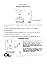
In addition, during the operating time of the filter pump the heating of the pool is controlled by the electronic
temperature control. The heating is switched off automatically by the internal interlocking during filtering
pauses. An adjustment control on the front cover can be used to select the desired temperature of the
swimming pool water or turn the heating off.
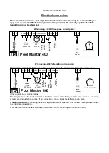
Another terminal enables accessories to be connected, e.g. feeders. The terminals D/D are floating contacts
and can therefore be used as needed. The relay contact between the terminals D/D is closed during the
filtering times and open outside the filtering times. Currents of up to 230V and outputs of up to 400W (cos
=1) can be put on this contact.
The terminals for the motor winding protection contact (WSK) enable a motor winding protection contact
switch to be connected, which is integrated into the motor winding of the filter pump. If this contact opens, e.g.
as result of the motor winding becoming excessively hot, the filter pump and with it the heading and the feeder
are switched off automatically as well. As soon as the motor winding protection contact closes after the motor
has cooled down, the units will switch on again automatically. A manual reset is not necessary. The terminals
WSK are allocated 230V.
Control lamps in the front cover indicate that the filter pump and the heating are operating, enabling
verification to be made at any time.
The filter pump is protected from overload by an electronic motor protection (current range infinitely variable
up to 8A).
Technical data:
Dimensions:
220mm x 219mm x 100mm
Operating voltage:
400V/50Hz
Power consumption of control system:
approx. 5VA
Switching capacity:
Pump:
max. 3,0 kW (AC3)
Heating:
max. 0,4 kW (AC1)
Protection class:
IP 40
Installation:
The control unit must be installed protected from moisture in accordance with its protection class. The ambient
temperature during operation may be between 0°C and 40°C and should be as constant as possible. The rel.
Humidity at the installation location must not exceed 95%. Condensation must not occur. Direct heat or solar
radiation to the device should be avoided. The power supply of the unit must be connected via an all-pole
main switch with a contact gap of at least 3 mm and an earth leakage protection switch with I
FN
30mA.
The unit must be isolated from supply before opening the case.

