Section 5 - Attachments and Hitches
5-16
31200205
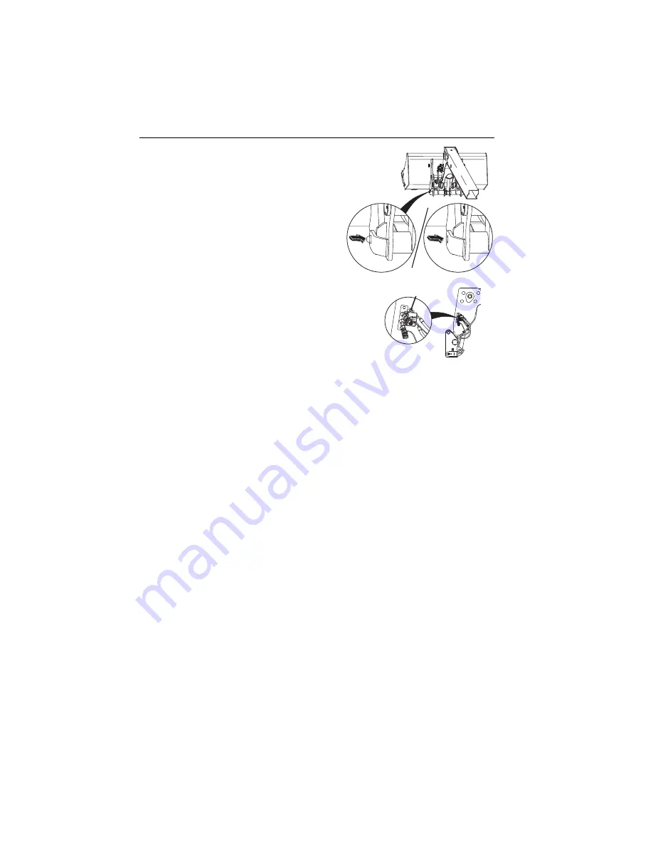
6. Raise boom to eye level and visually
check that the lock pin protrudes through
the hole. If the pin does not protrude
through the hole, place the attachment on
the ground and return to step 2.
7. Turn auxiliary hydraulic valve handle (
1
) forward,
away from the operator cab, to enable
attachment auxiliary hydraulics function.
8. If attachment is equipped, connect auxiliary hydraulic hoses. See
O
AL
1
9
3
0
DISENGAGED
ENGAGED
O
Z3
560
1
Summary of Contents for JLG 3508PS
Page 2: ......
Page 26: ...Section 1 General Safety Practices 1 14 31200205 This Page Intentionally Left Blank...
Page 45: ...Section 3 Controls and Indicators 3 9 31200205 This Page Intentionally Left Blank...
Page 68: ...Section 3 Controls and Indicators 3 32 31200205 This Page Intentionally Left Blank...
Page 85: ...Section 5 Attachments and Hitches 5 5 31200205 This Page Intentionally Left Blank...
Page 139: ...Section 7 Lubrication and Maintenance 7 7 31200205 17M OZ2430 EVERY 8...
Page 141: ...Section 7 Lubrication and Maintenance 7 9 31200205 17M OZ2440 2X 50 EVERY...
Page 160: ...Section 8 Additional Checks 8 6 31200205 This Page Intentionally Left Blank...
Page 174: ...Inspection Maintenance and Repair Log Date Comments...
Page 176: ......
Page 177: ......


