SECTION 4 - BOOM & PLATFORM
4-24
– JLG Lift –
3121659
3.
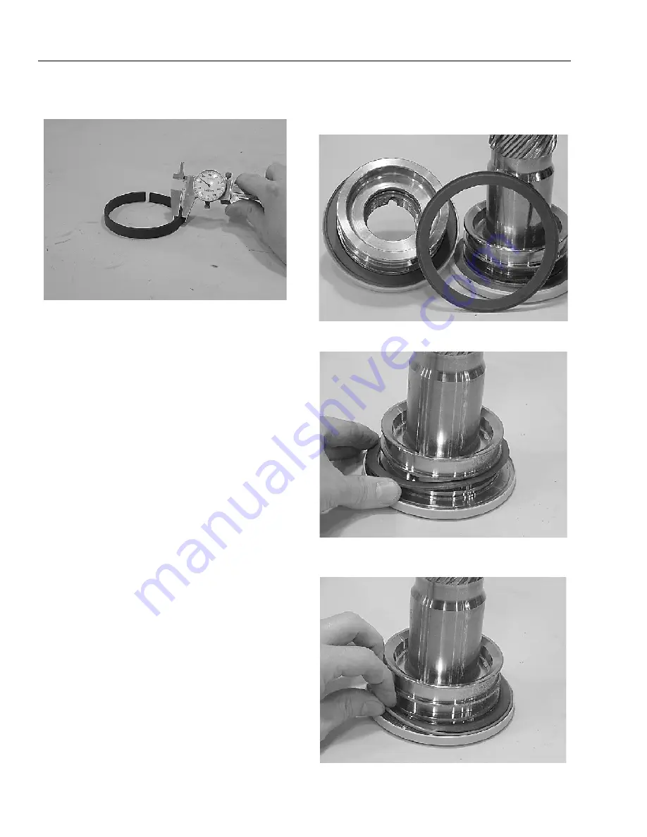
Inspect wear guide condition. Measure thickness not
less than 0.123" (3.12 mm).
Assembly
1.
Gather all components and tools to one location.
2.
Install thrust washer (16) on shaft (2) and end cap (4).
3.
Install exclusion seal (5) in groove on shaft (2) and end
cap (4) around outside edge of thrust washer (16).
Summary of Contents for JLG 450AJ
Page 2: ......
Page 32: ...SECTION 1 SPECIFICATIONS 1 18 JLG Lift 3121659 NOTES...
Page 80: ...SECTION 4 BOOM PLATFORM 4 2 JLG Lift 3121659 Figure 4 1 Boom Assembly...
Page 81: ...SECTION 4 BOOM PLATFORM 3121659 JLG Lift 4 3 Figure 4 2 Main Boom Assembly Sheet 1 of 2...
Page 82: ...SECTION 4 BOOM PLATFORM 4 4 JLG Lift 3121659 Figure 4 3 Main Boom Assembly Sheet 2 of 2...
Page 83: ...SECTION 4 BOOM PLATFORM 3121659 JLG Lift 4 5 Figure 4 4 Upper Boom Assembly...
Page 84: ...SECTION 4 BOOM PLATFORM 4 6 JLG Lift 3121659 Figure 4 5 Jib Assembly...
Page 118: ...SECTION 4 BOOM PLATFORM 4 40 JLG Lift 3121659 NOTES...
Page 156: ...SECTION 5 BASIC HYDRAULIC INFORMATION HYDRAULIC SCHEMATICS 5 38 JLG Lift 3121659 NOTES...
Page 164: ...SECTION 6 JLG CONTROL SYSTEM 6 8 JLG Lift 3121659 Figure 6 2 Tilt Sensor Location...
Page 169: ...SECTION 6 JLG CONTROL SYSTEM 3121659 JLG Lift 6 13 Figure 6 7 Analyzer Connecting Points...
Page 181: ...SECTION 6 JLG CONTROL SYSTEM 3121659 JLG Lift 6 25 Figure 6 19 Platform Module Sheet 1 of 2...
Page 182: ...SECTION 6 JLG CONTROL SYSTEM 6 26 JLG Lift 3121659 Figure 6 20 Platform Module Sheet 2 of 2...
Page 224: ...SECTION 6 JLG CONTROL SYSTEM 6 68 JLG Lift 3121659 NOTES...
Page 340: ...SECTION 7 BASIC ELECTRICAL INFORMATION ELECTRICAL SCHEMATICS 7 116 JLG Lift 3121659 NOTES...
Page 341: ......


