SECTION 6 - JLG CONTROL SYSTEM
6-4
– JLG Lift –
3121659
Press
ENTER
to select the
ACCESS LEVEL
menu.
Using the
UP
or
DOWN
arrow keys, enter the first
digit of the password, 3.
Then using the
RIGHT
arrow key, position the cursor to
the right one space to enter the second digit of the password.
Use the
UP
or
DOWN
arrow key to enter the sec-
ond digit of the password which is 33271.
Once the correct password is displayed, press
ENTER
.
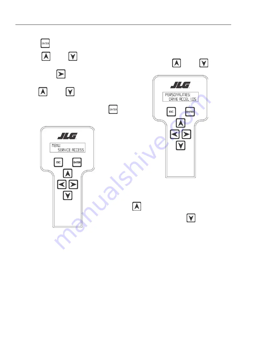
The access level should display the following, if the password
was entered correctly:
MENU:
SERVICE ACCESS
Repeat the above steps if the correct access level is not dis-
played or you can not adjust the personality settings.
Adjusting Parameters Using the Hand Held
Analyzer
Once you have gained access to level 1, and a personality item
is selected, press the
UP
or
DOWN
arrow keys to
adjust its value, for example:
DRIVE:
ACCEL 1.5s
There will be a minimum and maximum for the value to
ensure efficient operation. The Value will not increase if the
UP
arrow is pressed when at the maximum value nor will
the value decrease if the
DOWN
arrow is pressed and
the value is at the minimum value for any particular personal-
ity. If the value does not change when pressing the up and
down arrows, check the access level to ensure you are at
access level 1.
Summary of Contents for JLG 450AJ
Page 2: ......
Page 32: ...SECTION 1 SPECIFICATIONS 1 18 JLG Lift 3121659 NOTES...
Page 80: ...SECTION 4 BOOM PLATFORM 4 2 JLG Lift 3121659 Figure 4 1 Boom Assembly...
Page 81: ...SECTION 4 BOOM PLATFORM 3121659 JLG Lift 4 3 Figure 4 2 Main Boom Assembly Sheet 1 of 2...
Page 82: ...SECTION 4 BOOM PLATFORM 4 4 JLG Lift 3121659 Figure 4 3 Main Boom Assembly Sheet 2 of 2...
Page 83: ...SECTION 4 BOOM PLATFORM 3121659 JLG Lift 4 5 Figure 4 4 Upper Boom Assembly...
Page 84: ...SECTION 4 BOOM PLATFORM 4 6 JLG Lift 3121659 Figure 4 5 Jib Assembly...
Page 118: ...SECTION 4 BOOM PLATFORM 4 40 JLG Lift 3121659 NOTES...
Page 156: ...SECTION 5 BASIC HYDRAULIC INFORMATION HYDRAULIC SCHEMATICS 5 38 JLG Lift 3121659 NOTES...
Page 164: ...SECTION 6 JLG CONTROL SYSTEM 6 8 JLG Lift 3121659 Figure 6 2 Tilt Sensor Location...
Page 169: ...SECTION 6 JLG CONTROL SYSTEM 3121659 JLG Lift 6 13 Figure 6 7 Analyzer Connecting Points...
Page 181: ...SECTION 6 JLG CONTROL SYSTEM 3121659 JLG Lift 6 25 Figure 6 19 Platform Module Sheet 1 of 2...
Page 182: ...SECTION 6 JLG CONTROL SYSTEM 6 26 JLG Lift 3121659 Figure 6 20 Platform Module Sheet 2 of 2...
Page 224: ...SECTION 6 JLG CONTROL SYSTEM 6 68 JLG Lift 3121659 NOTES...
Page 340: ...SECTION 7 BASIC ELECTRICAL INFORMATION ELECTRICAL SCHEMATICS 7 116 JLG Lift 3121659 NOTES...
Page 341: ......


