SECTION 3 - CHASSIS & TURNTABLE
3-8
– JLG Lift –
3121659
Cover Disassembly
1.
Remove two bolts (6C) holding disconnect cap (6D) to
cover (6A).
2.
Remove disconnect cap (6D) from on top of cover cap
(6B) and cover (6A).
3.
Remove two bolts (6C) holding cover cap (6B) to cover
(6A).
4.
Remove cover cap (6B) from cover (6A).
5.
Remove disconnect rod (6K) from cover cap (6B).
6.
Pry O-ring (6F) out of groove inside cover cap (6B). Dis-
card O-ring.
7.
Remove O-ring (6G) from flange of cover cap (6B). Dis-
card O-ring.
8.
Remove pipe plug (6H) from cover (6A).
9.
Cover disassembly is complete.
Carrier Disassembly
NOTE:
Discard old needle rollers and use new ones during reas-
sembly.
1.
Using a punch and hammer, drive roll pin (3G) into
planet shaft (3E).
DRIVE ROLL PIN ALL THE WAY INTO PLANET SHAFT OR CARRIER WILL BE
DAMAGED WHEN PLANET SHAFT IS REMOVED.
2.
Using a punch and hammer, drive planet shaft (3E) out
of planet shaft hole in carrier housing (3A).
3.
When you remove
planet shaft (3E) from carrier housing,
one thrust washer (38), one cluster gear (3F), and one
more thrust washer (3B) will come off planet shaft and
come to rest inside carrier. Remove these parts from
inside carrier.
4.
Remove 16 needle rollers (3C) from inside one end of
cluster gear (3F). Discard needle rollers.
5.
Remove one spacer (3D) from inside cluster gear (3F).
6.
Remove remaining 16 needle rollers (3C) from other side
of cluster gear (3F). Discard needle rollers.
7.
Repeat steps 1-6 to remove and disassemble two
remaining cluster gears.
8.
At this point carrier disassembly is complete.
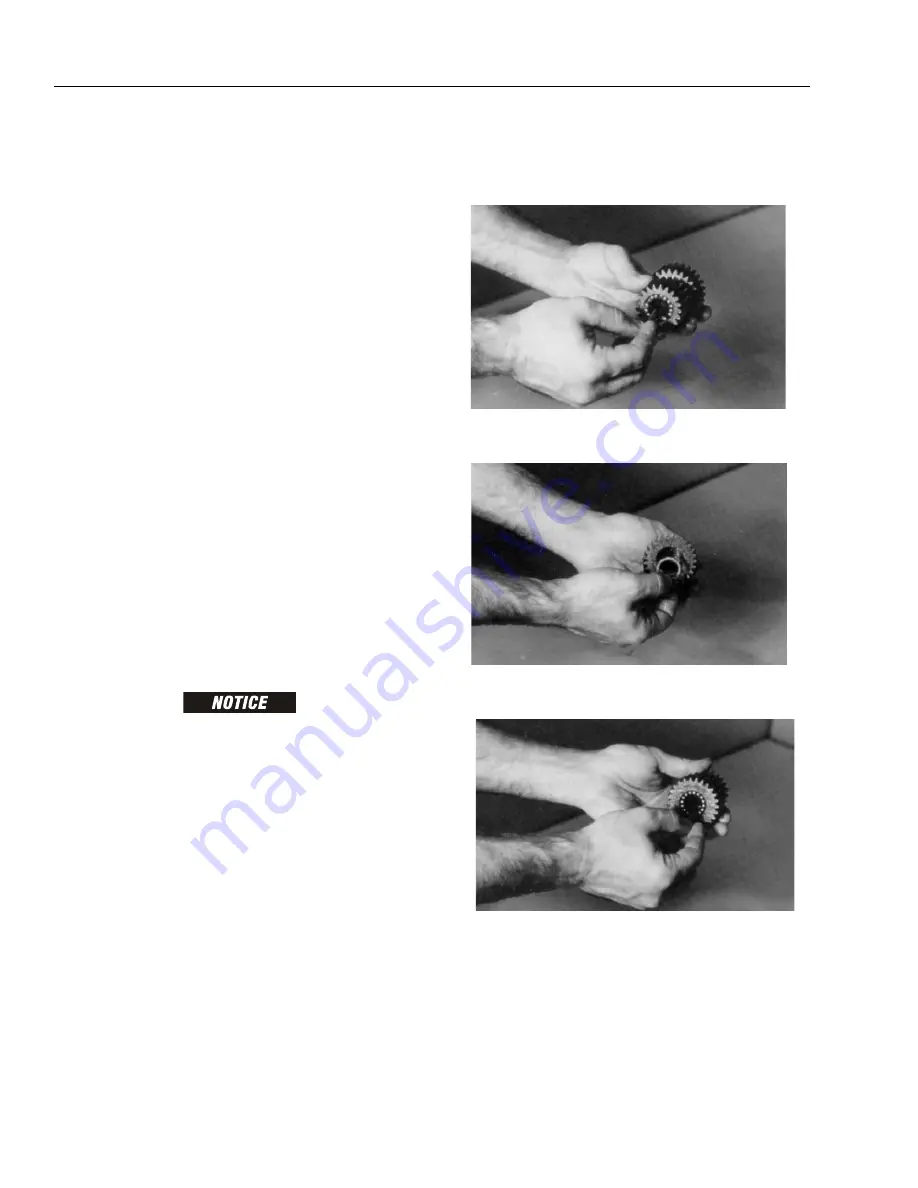
Assemble Carrier
1.
Apply grease to inside of one cluster gear (3F) and line one
half of cluster gear with 16 needle rollers (3C).
2.
Place spacer (3D) inside cluster gear (3F) so it rests on
top of needle rollers.
3.
Line remaining half of cluster gear (3F) with 16 needle
rollers.
Summary of Contents for JLG 450AJ
Page 2: ......
Page 32: ...SECTION 1 SPECIFICATIONS 1 18 JLG Lift 3121659 NOTES...
Page 80: ...SECTION 4 BOOM PLATFORM 4 2 JLG Lift 3121659 Figure 4 1 Boom Assembly...
Page 81: ...SECTION 4 BOOM PLATFORM 3121659 JLG Lift 4 3 Figure 4 2 Main Boom Assembly Sheet 1 of 2...
Page 82: ...SECTION 4 BOOM PLATFORM 4 4 JLG Lift 3121659 Figure 4 3 Main Boom Assembly Sheet 2 of 2...
Page 83: ...SECTION 4 BOOM PLATFORM 3121659 JLG Lift 4 5 Figure 4 4 Upper Boom Assembly...
Page 84: ...SECTION 4 BOOM PLATFORM 4 6 JLG Lift 3121659 Figure 4 5 Jib Assembly...
Page 118: ...SECTION 4 BOOM PLATFORM 4 40 JLG Lift 3121659 NOTES...
Page 156: ...SECTION 5 BASIC HYDRAULIC INFORMATION HYDRAULIC SCHEMATICS 5 38 JLG Lift 3121659 NOTES...
Page 164: ...SECTION 6 JLG CONTROL SYSTEM 6 8 JLG Lift 3121659 Figure 6 2 Tilt Sensor Location...
Page 169: ...SECTION 6 JLG CONTROL SYSTEM 3121659 JLG Lift 6 13 Figure 6 7 Analyzer Connecting Points...
Page 181: ...SECTION 6 JLG CONTROL SYSTEM 3121659 JLG Lift 6 25 Figure 6 19 Platform Module Sheet 1 of 2...
Page 182: ...SECTION 6 JLG CONTROL SYSTEM 6 26 JLG Lift 3121659 Figure 6 20 Platform Module Sheet 2 of 2...
Page 224: ...SECTION 6 JLG CONTROL SYSTEM 6 68 JLG Lift 3121659 NOTES...
Page 340: ...SECTION 7 BASIC ELECTRICAL INFORMATION ELECTRICAL SCHEMATICS 7 116 JLG Lift 3121659 NOTES...
Page 341: ......


