SECTION 7 - BASIC ELECTRICAL INFORMATION & ELECTRICAL SCHEMATICS
3121659
– JLG Lift –
7-5
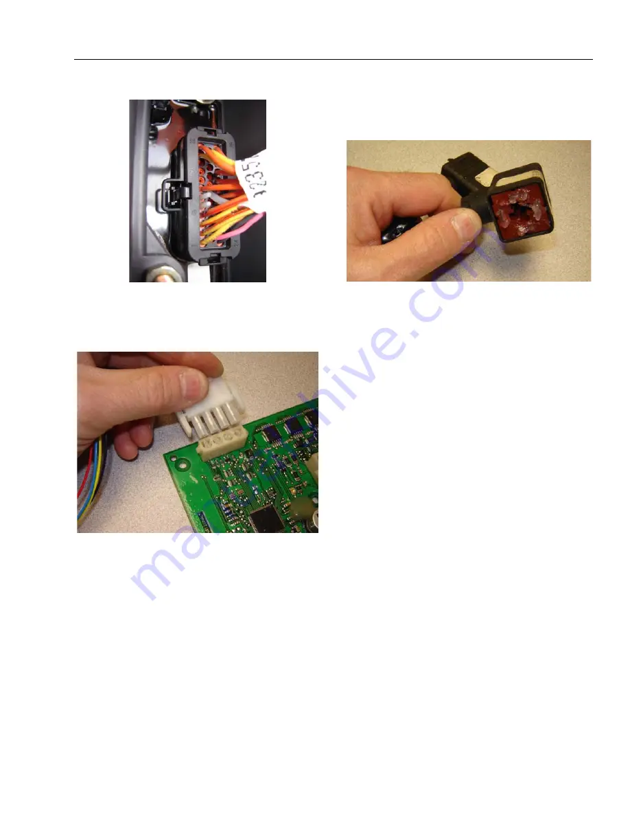
AMP Mate-N-Lok
Follow the installation instructions.
DIN Connectors
This connector is typically used on hydraulic valves. Follow the
installation instructions.
Exclusions
A limited number of connectors do not benefit from dielectric
grease, or may be permanently damaged by application.
Dielectric grease may not be required in properly sealed
enclosures.
Figure 7-6. Use of Seal Plugs
Summary of Contents for JLG 450AJ
Page 2: ......
Page 32: ...SECTION 1 SPECIFICATIONS 1 18 JLG Lift 3121659 NOTES...
Page 80: ...SECTION 4 BOOM PLATFORM 4 2 JLG Lift 3121659 Figure 4 1 Boom Assembly...
Page 81: ...SECTION 4 BOOM PLATFORM 3121659 JLG Lift 4 3 Figure 4 2 Main Boom Assembly Sheet 1 of 2...
Page 82: ...SECTION 4 BOOM PLATFORM 4 4 JLG Lift 3121659 Figure 4 3 Main Boom Assembly Sheet 2 of 2...
Page 83: ...SECTION 4 BOOM PLATFORM 3121659 JLG Lift 4 5 Figure 4 4 Upper Boom Assembly...
Page 84: ...SECTION 4 BOOM PLATFORM 4 6 JLG Lift 3121659 Figure 4 5 Jib Assembly...
Page 118: ...SECTION 4 BOOM PLATFORM 4 40 JLG Lift 3121659 NOTES...
Page 156: ...SECTION 5 BASIC HYDRAULIC INFORMATION HYDRAULIC SCHEMATICS 5 38 JLG Lift 3121659 NOTES...
Page 164: ...SECTION 6 JLG CONTROL SYSTEM 6 8 JLG Lift 3121659 Figure 6 2 Tilt Sensor Location...
Page 169: ...SECTION 6 JLG CONTROL SYSTEM 3121659 JLG Lift 6 13 Figure 6 7 Analyzer Connecting Points...
Page 181: ...SECTION 6 JLG CONTROL SYSTEM 3121659 JLG Lift 6 25 Figure 6 19 Platform Module Sheet 1 of 2...
Page 182: ...SECTION 6 JLG CONTROL SYSTEM 6 26 JLG Lift 3121659 Figure 6 20 Platform Module Sheet 2 of 2...
Page 224: ...SECTION 6 JLG CONTROL SYSTEM 6 68 JLG Lift 3121659 NOTES...
Page 340: ...SECTION 7 BASIC ELECTRICAL INFORMATION ELECTRICAL SCHEMATICS 7 116 JLG Lift 3121659 NOTES...
Page 341: ......


