SECTION 4 - BOOM & PLATFORM
3121827
– JLG Lift –
4-23
Installing Counterbalance Valve
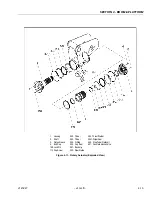
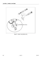
Refer to Figure 4-13., Rotator Counterbalance Valve.
1.
Make sure the surface of the actuator is clean, free
of any contamination and foreign debris including
old Loctite.
2.
Make sure the new valve has the O-rings in the
counterbores of the valve to seal it to the actuator
housing.
3.
The bolts that come with the valve are grade 8 bolts.
New bolts should be installed with a new valve. Loc-
tite #242 should be applied to the shank of the three
bolts at the time of installation.
4.
Torque the 1/4-inch bolts 110 to 120 inch pounds
(12.4 to 13.5 Nm). Do not torque over 125 inch
pounds (14.1 Nm). Torque the 5/16-inch bolts 140
inch pounds (15.8 Nm). Do not torque over 145 inch
pounds (16.3 Nm).
Testing the Actuator
If the equipment is available, the actuator should be tested
on a hydraulic test bench. The breakaway pressure — the
pressure at which the shaft begins to rotate — should be
approximately 400 psi (28 bar). Cycle the actuator at least
25 times at 3000 psi (210 bar) pressure. After the 25 rota-
tions, increase the pressure to 4500 psi (315 bar) to check
for leaks and cracks. Perform the test again at the end of
the rotation in the opposite direction.
TESTING THE ACTUATOR FOR INTERNAL
LEAKAGE
If the actuator is equipped with a counterbalance valve,
plug the valve ports. Connect the hydraulic lines to the
housing ports. Bleed all air from the actuator (see Installa-
tion and Bleeding) Rotate the shaft to the end of rotation
at 3000 psi (210 bar) and maintain pressure. Remove the
hydraulic line from the non-pressurized side.
Continuous oil flow from the open housing port indicates
internal leakage across the piston. Replace the line and
rotate the shaft to the end of rotation in the opposite direc-
tion. Repeat the test procedure outlined above for the
other port. If there is an internal leak, disassemble, inspect
and repair.
Summary of Contents for JLG E400AJP
Page 2: ......
Page 32: ...SECTION 1 SPECIFICATIONS 1 18 JLG Lift 3121827 NOTES...
Page 42: ...SECTION 2 GENERAL 2 10 JLG Lift 3121827 NOTES...
Page 54: ...SECTION 3 CHASSIS TURNTABLE 3 12 JLG Lift 3121827 Figure 3 3 Speed Sensor Orientation...
Page 60: ...SECTION 3 CHASSIS TURNTABLE 3 18 JLG Lift 3121827 Figure 3 7 Steering Components and Spindles...
Page 62: ...SECTION 3 CHASSIS TURNTABLE 3 20 JLG Lift 3121827 Figure 3 9 Tilt Sensor Location...
Page 86: ...SECTION 3 CHASSIS TURNTABLE 3 44 JLG Lift 3121827 Figure 3 16 Swing Components...
Page 88: ...SECTION 3 CHASSIS TURNTABLE 3 46 JLG Lift 3121827 Figure 3 18 Battery Cable Connections...
Page 90: ...SECTION 3 CHASSIS TURNTABLE 3 48 JLG Lift 3121827 Figure 3 20 On Board Generator...
Page 97: ...SECTION 3 CHASSIS TURNTABLE 3121827 JLG Lift 3 55 Figure 3 22 Generator Components...
Page 116: ...SECTION 3 CHASSIS TURNTABLE 3 74 JLG Lift 3121827 NOTES...
Page 127: ...SECTION 4 BOOM PLATFORM 3121827 JLG Lift 4 11 Figure 4 10 Boom Limit Switches...
Page 140: ...SECTION 4 BOOM PLATFORM 4 24 JLG Lift 3121827 Figure 4 13 Rotator Counterbalance Valve...
Page 178: ...SECTION 5 HYDRAULICS 5 24 JLG Lift 3121827 Figure 5 26 HydraForce Cartridge Torque Value Chart...
Page 214: ...SECTION 6 JLG CONTROL SYSTEM 6 34 JLG Lift 3121827 NOTES...
Page 257: ......


