SECTION 1 - SPECIFICATIONS
3121827
– JLG Lift –
1-3
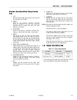
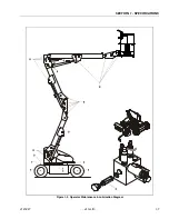
Machine Orientation When Doing Function
Tests
1. LIFT:
Boom retracted, telescope retracted. Lift up, record
time. Lift down, record time.
2. SWING:
Boom at full elevation, telescope retracted.
Swing the turntable to the end stop. Swing the
opposite direction. Record time. Swing the other
direction, record time.
3. TELESCOPE:
Boom at full elevation, telescope retracted. Tele-
scope out, record time. Telescope in, record time.
4. DRIVE:
Test should be done on a smooth, level surface.
Start approximately 25 feet from starting point so
that the unit is at a maximum speed when starting
the test. Results should be recorded for a 200 foot
course. Drive forward, record time. Drive reverse,
record time.
5. DRIVE (ABOVE HORIZONTAL):
Test should be done on a smooth, level surface. The
platform speed control knob should be selected out
of creep speed. This verifies that the switches are
working when the boom is above horizontal.
Results should be recorded for a 50 ft. course. Drive
forward, record time. Drive reverse, record time.
6. PLATFORM ROTATE:
Platform level and completely rotated one direction.
Rotate the opposite direction, record time. Rotate
the other direction, record time.
7. JIB:
Platform level and centered with the boom. Start
with the jib down. Jib up, record time. Jib down,
record time.
8. LOWER LIFT:
Upper boom horizontal, telescoped in. Lower lift up,
record time. Lower lift down, record time.
9. JIB SWING:
Platform level and centered with the boom. Start
with the jib horizontal. Begin with jib swing fully to
left. Swing fully to right. Record time. Swing to the
left, record time.
NOTE:
Stop watch should be started with the function, not
with the controller or switch.
All speed tests are run from the platform.
The platform speed control knob must be at full
speed. (turned clockwise completely)
The function speeds may vary due to cold thick
hydraulic oil. Tests should be run with oil tempera-
ture above 100
o
F. (38
o
C)
Some flow control functions may not work with the
speed control knob in the creep position.
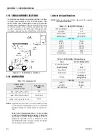
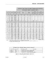
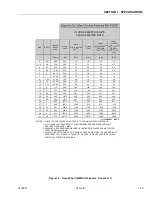
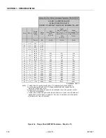
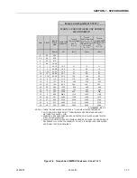
1.10 TORQUE SPECIFICATIONS
* Check swing bearing bolts for security after first 50
hours of operation and every 600 hours thereafter.
Table 1-10. Torque Requirements
Description
Torque Value
Interval Hours
Wheel Lugs
170 ft. lbs. (230 Nm)
150
Swing Bearing (Loctite)
190 ft. lbs.(260Nm)
50/600*
Summary of Contents for JLG E400AJP
Page 2: ......
Page 32: ...SECTION 1 SPECIFICATIONS 1 18 JLG Lift 3121827 NOTES...
Page 42: ...SECTION 2 GENERAL 2 10 JLG Lift 3121827 NOTES...
Page 54: ...SECTION 3 CHASSIS TURNTABLE 3 12 JLG Lift 3121827 Figure 3 3 Speed Sensor Orientation...
Page 60: ...SECTION 3 CHASSIS TURNTABLE 3 18 JLG Lift 3121827 Figure 3 7 Steering Components and Spindles...
Page 62: ...SECTION 3 CHASSIS TURNTABLE 3 20 JLG Lift 3121827 Figure 3 9 Tilt Sensor Location...
Page 86: ...SECTION 3 CHASSIS TURNTABLE 3 44 JLG Lift 3121827 Figure 3 16 Swing Components...
Page 88: ...SECTION 3 CHASSIS TURNTABLE 3 46 JLG Lift 3121827 Figure 3 18 Battery Cable Connections...
Page 90: ...SECTION 3 CHASSIS TURNTABLE 3 48 JLG Lift 3121827 Figure 3 20 On Board Generator...
Page 97: ...SECTION 3 CHASSIS TURNTABLE 3121827 JLG Lift 3 55 Figure 3 22 Generator Components...
Page 116: ...SECTION 3 CHASSIS TURNTABLE 3 74 JLG Lift 3121827 NOTES...
Page 127: ...SECTION 4 BOOM PLATFORM 3121827 JLG Lift 4 11 Figure 4 10 Boom Limit Switches...
Page 140: ...SECTION 4 BOOM PLATFORM 4 24 JLG Lift 3121827 Figure 4 13 Rotator Counterbalance Valve...
Page 178: ...SECTION 5 HYDRAULICS 5 24 JLG Lift 3121827 Figure 5 26 HydraForce Cartridge Torque Value Chart...
Page 214: ...SECTION 6 JLG CONTROL SYSTEM 6 34 JLG Lift 3121827 NOTES...
Page 257: ......


