SECTION 5 - HYDRAULICS
3121827
– JLG Lift –
5-21
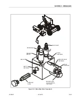
Platform Level Down Relief
1.
On machines prior to S/N 0300062642, install the
pressure gauge at the “G” port on Main Control
valve, activate and bottom out Platform Level Down.
On machines S/N 0300062642 to present, install the
pressure gauge at the "B1" port on the back of the
Main Control Valve, activate and bottom out Platform
Level Down.
2.
Adjust Platform Level Down Relief to value given in
Table 5-4, Pressure Settings - Prior to S/N
0300062642 or Table 5-5, Pressure Settings - S/N
0300062642 to Present.
Steer Relief
1.
With pressure gauge at “G” port on steer/brake
valve, activate and bottom out Steer Left or Right.
2.
3.
Shut down hydraulic system and remove pressure
gauge.
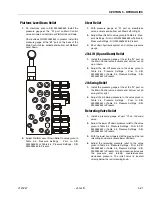
Jib Lift (Up and Down) Relief
1.
Install the pressure gauge at the at the "G" port on
the Main Control valve, activate and bottom out jib
up or down.
2.
Adjust the Jib LIft pressure to the value given in
Table 5-4, Pressure Settings - Prior to S/N
0300062642 or Table 5-5, Pressure Settings - S/N
0300062642 to Present.
Jib Swing Relief
1.
Install the pressure gauge at the at the "G" port on
the Main Control valve, activate and bottom out jib
swing left or right.
2.
Adjust the Jib Swing pressure to the value given in
Table 5-4, Pressure Settings - Prior to S/N
0300062642 or Table 5-5, Pressure Settings - S/N
0300062642 to Present.
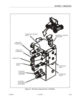
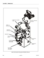
Releveling Valve Relief
1.
Install a pressure gauge at port "G" on the main
valve.
2.
Adjust the lower lift down pressure relief to the value
given in Table 5-4, Pressure Settings - Prior to S/N
0300062642 or Table 5-5, Pressure Settings - S/N
0300062642 to Present.
3.
With the lower boom lowered all the way, pull the red
releveling knob and activate lower lift down.
4.
Adjust the releveling pressure relief to the value
given in Table 5-4, Pressure Settings - Prior to S/N
0300062642 or Table 5-5, Pressure Settings - S/N
0300062642 to Present. Turning clockwise increases
the pressure and turning counterclockwise
decreases pressure. The relief valve is located
directly below the red releveling knob.
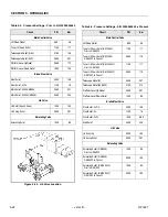
LC
LR
TR
T2
B2
B1
S2
S1
R2
R1
TC
LU
LL
P
R
L
T1
17
Summary of Contents for JLG E400AJP
Page 2: ......
Page 32: ...SECTION 1 SPECIFICATIONS 1 18 JLG Lift 3121827 NOTES...
Page 42: ...SECTION 2 GENERAL 2 10 JLG Lift 3121827 NOTES...
Page 54: ...SECTION 3 CHASSIS TURNTABLE 3 12 JLG Lift 3121827 Figure 3 3 Speed Sensor Orientation...
Page 60: ...SECTION 3 CHASSIS TURNTABLE 3 18 JLG Lift 3121827 Figure 3 7 Steering Components and Spindles...
Page 62: ...SECTION 3 CHASSIS TURNTABLE 3 20 JLG Lift 3121827 Figure 3 9 Tilt Sensor Location...
Page 86: ...SECTION 3 CHASSIS TURNTABLE 3 44 JLG Lift 3121827 Figure 3 16 Swing Components...
Page 88: ...SECTION 3 CHASSIS TURNTABLE 3 46 JLG Lift 3121827 Figure 3 18 Battery Cable Connections...
Page 90: ...SECTION 3 CHASSIS TURNTABLE 3 48 JLG Lift 3121827 Figure 3 20 On Board Generator...
Page 97: ...SECTION 3 CHASSIS TURNTABLE 3121827 JLG Lift 3 55 Figure 3 22 Generator Components...
Page 116: ...SECTION 3 CHASSIS TURNTABLE 3 74 JLG Lift 3121827 NOTES...
Page 127: ...SECTION 4 BOOM PLATFORM 3121827 JLG Lift 4 11 Figure 4 10 Boom Limit Switches...
Page 140: ...SECTION 4 BOOM PLATFORM 4 24 JLG Lift 3121827 Figure 4 13 Rotator Counterbalance Valve...
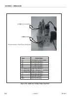
Page 178: ...SECTION 5 HYDRAULICS 5 24 JLG Lift 3121827 Figure 5 26 HydraForce Cartridge Torque Value Chart...
Page 214: ...SECTION 6 JLG CONTROL SYSTEM 6 34 JLG Lift 3121827 NOTES...
Page 257: ......

