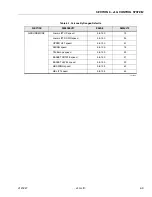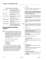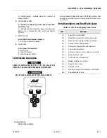
SECTION 6 - JLG CONTROL SYSTEM
6-14
– JLG Lift –
3121827
2/5
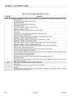
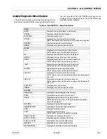
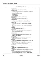
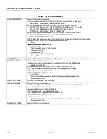
Flash code 2/5 indicates that a function is prevented due to a cutout.
BOOM PREVENTED - DRIVE SELECTED
A boom function is selected while a drive function is selected and drive cutout is configured to prevent
simultaneous drive & boom operation.
BOOM PREVENTED - FUNCTION CUTOUT ACTIVE
A boom function is selected while function cutout is active and configured to cutout boom functions.
DRIVE & BOOM PREVENTED - FUNCTION CUTOUT ACTIVE
Drive or a boom function is selected while function cutout is active and configured to cutout all functions.
DRIVE PREVENTED - ABOVE ELEVATION
Drive is selected while above elevation and drive cutout is configured to prevent drive.
DRIVE PREVENTED - BOOM MOVEMENT SELECTED
Drive is selected while a boom function is selected and drive cutout is configured to prevent simultaneous
drive & boom operation.
DRIVE PREVENTED - CHARGER CONNECTED
Drive is selected while the charger is on (indicated by drive cutout being active) and drive cutout is config-
ured to prevent drive.
DRIVE PREVENTED - TILTED AND ABOVE ELEVATION
Drive is selected while drive cutout is active and drive cutout is configured to prevent drive.
TILT MODULE FAILURE: NOT COMMUNICATING
There is a problem with the positrac/tilt module; the controller defaults to massively tilted and does not try to
prevent vehicle roll on the grade.
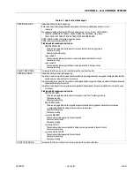
3/1
Flash code 3/1 indicates that a contactor did not close when energized.
LINE & DIRECTION CONTACTORS MISWIRED
When the line contactor was closed traction point A went high (and the capacitor bank charge did not
increase to battery supply) - this occurs if the line contactor coil wiring is swapped with that for a direction
contactor coil.
OPEN-CIRCUIT FORWARD DIRECTION CONTACTOR OR TRACTION MOTOR
Traction point A did not go high when forward contactor was energized (this could be due to traction motor
open-circuit or a power wiring error).
OPEN-CIRCUIT LINE CONTACTOR OR TRACTION MOTOR
The capacitor bank charge did not increase to battery supply when line contactor was energized (this could
be due to a power wiring error).
OPEN-CIRCUIT REVERSE DIRECTION CONTACTOR
Traction point A did not go high when reverse contactor was energized (this could be due to traction motor
open-circuit or a power wiring error).
3/2
Flash code 3/2 indicates that a contactor did not open when energized.
WELDED LINE CONTACTOR
The capacitor bank charge did not decrease from battery supply when line contactor was deenergized (this
could be due to a power wiring error).
WARNING: If the line contactor is welded, the controller will not switch off when EMS or keyswitch is turned
off.
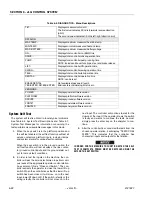
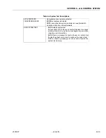
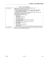
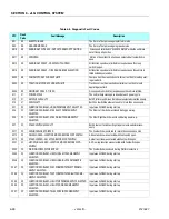
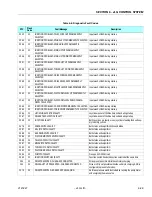
Table 6-4. Help Descriptions and Fault Flash Codes
Summary of Contents for JLG E400AJP
Page 2: ......
Page 32: ...SECTION 1 SPECIFICATIONS 1 18 JLG Lift 3121827 NOTES...
Page 42: ...SECTION 2 GENERAL 2 10 JLG Lift 3121827 NOTES...
Page 54: ...SECTION 3 CHASSIS TURNTABLE 3 12 JLG Lift 3121827 Figure 3 3 Speed Sensor Orientation...
Page 60: ...SECTION 3 CHASSIS TURNTABLE 3 18 JLG Lift 3121827 Figure 3 7 Steering Components and Spindles...
Page 62: ...SECTION 3 CHASSIS TURNTABLE 3 20 JLG Lift 3121827 Figure 3 9 Tilt Sensor Location...
Page 86: ...SECTION 3 CHASSIS TURNTABLE 3 44 JLG Lift 3121827 Figure 3 16 Swing Components...
Page 88: ...SECTION 3 CHASSIS TURNTABLE 3 46 JLG Lift 3121827 Figure 3 18 Battery Cable Connections...
Page 90: ...SECTION 3 CHASSIS TURNTABLE 3 48 JLG Lift 3121827 Figure 3 20 On Board Generator...
Page 97: ...SECTION 3 CHASSIS TURNTABLE 3121827 JLG Lift 3 55 Figure 3 22 Generator Components...
Page 116: ...SECTION 3 CHASSIS TURNTABLE 3 74 JLG Lift 3121827 NOTES...
Page 127: ...SECTION 4 BOOM PLATFORM 3121827 JLG Lift 4 11 Figure 4 10 Boom Limit Switches...
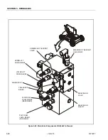
Page 140: ...SECTION 4 BOOM PLATFORM 4 24 JLG Lift 3121827 Figure 4 13 Rotator Counterbalance Valve...
Page 178: ...SECTION 5 HYDRAULICS 5 24 JLG Lift 3121827 Figure 5 26 HydraForce Cartridge Torque Value Chart...
Page 214: ...SECTION 6 JLG CONTROL SYSTEM 6 34 JLG Lift 3121827 NOTES...
Page 257: ......

