SECTION 7 - BASIC TROUBLESHOOTING, ELECTRICAL INFORMATION, & SCHEMATICS
7-10
– JLG Lift –
3121827
.
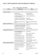
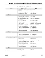
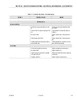
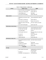
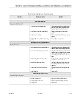
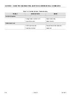
Table 7-4. Chassis Assembly - Troubleshooting
TROUBLE
PROBABLE CAUSE
REMEDY
GENERATOR.
Engine will not start.
Enable switch is open.
Actuate switch.
Fuses open.
Determine and correct cause; replace fuse.
Ground EMS is open.
Pull out EMS to activate.
Defective starter motor.
Replace starter motor.
Damaged wiring in ignition circuit (broken wire
on starter).
Repair, replace wiring.
Manual start switch not functioning properly.
Replace switch/check wiring.
Ignition relay not functioning properly.
Replace relay.
Ignition circuit shorted to ground.
See proper wiring diagram.
Battery cable(s) not making contact.
Clean and tighten cable(s).
Engine will not start (ignition OK).
No fuel.
Replenish fuel as necessary.
Clogged fuel filter.
Replace fuel filter.
Choke solenoid malfunction.
Replace choke solenoid.
Restricted or broken fuel line.
Clean or replace fuel line.
Fuel shut-off valve in carburetor stuck or frozen.
Repair or replace fuel shut-off. Check for electri-
cal power.
Battery discharged.
Charge battery, replace if defective.
Cam timing belt jumped time or broken.
Repair or replace timing belt.
Ignition timing slipped.
Repair timing.
Engine surges.
Governor not adjusted properly.
Correctly adjust governor.
Strong fuel odor.
Fuel tank overfilled.
Check fuel tank and immediately wipe up spilled
fuel.
Fuel tank damaged.
Drain all fuel from tank and remove tank for
replacement or repair.
Fuel line from tank damaged.
Replace fuel line.
Carburetor flooding.
Repair, replace or adjust carburetor.
Summary of Contents for JLG E400AJP
Page 2: ......
Page 32: ...SECTION 1 SPECIFICATIONS 1 18 JLG Lift 3121827 NOTES...
Page 42: ...SECTION 2 GENERAL 2 10 JLG Lift 3121827 NOTES...
Page 54: ...SECTION 3 CHASSIS TURNTABLE 3 12 JLG Lift 3121827 Figure 3 3 Speed Sensor Orientation...
Page 60: ...SECTION 3 CHASSIS TURNTABLE 3 18 JLG Lift 3121827 Figure 3 7 Steering Components and Spindles...
Page 62: ...SECTION 3 CHASSIS TURNTABLE 3 20 JLG Lift 3121827 Figure 3 9 Tilt Sensor Location...
Page 86: ...SECTION 3 CHASSIS TURNTABLE 3 44 JLG Lift 3121827 Figure 3 16 Swing Components...
Page 88: ...SECTION 3 CHASSIS TURNTABLE 3 46 JLG Lift 3121827 Figure 3 18 Battery Cable Connections...
Page 90: ...SECTION 3 CHASSIS TURNTABLE 3 48 JLG Lift 3121827 Figure 3 20 On Board Generator...
Page 97: ...SECTION 3 CHASSIS TURNTABLE 3121827 JLG Lift 3 55 Figure 3 22 Generator Components...
Page 116: ...SECTION 3 CHASSIS TURNTABLE 3 74 JLG Lift 3121827 NOTES...
Page 127: ...SECTION 4 BOOM PLATFORM 3121827 JLG Lift 4 11 Figure 4 10 Boom Limit Switches...
Page 140: ...SECTION 4 BOOM PLATFORM 4 24 JLG Lift 3121827 Figure 4 13 Rotator Counterbalance Valve...
Page 178: ...SECTION 5 HYDRAULICS 5 24 JLG Lift 3121827 Figure 5 26 HydraForce Cartridge Torque Value Chart...
Page 214: ...SECTION 6 JLG CONTROL SYSTEM 6 34 JLG Lift 3121827 NOTES...
Page 257: ......

