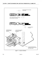
SECTION 7 - BASIC TROUBLESHOOTING, ELECTRICAL INFORMATION, & SCHEMATICS
3121827
– JLG Lift –
7-11
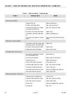
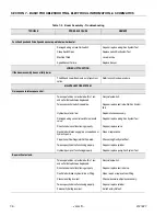
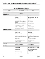
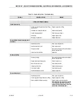
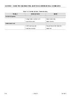
FRONT FRAME AXLE AREA.
One or both wheels will not steer.
Steering link or tie rod broken or attaching hard-
ware missing.
Replace steering link, tie rod or hardware as nec-
essary.
One or both front wheels will not rotate or
rotate erratically.
Wheel hub or bearings damaged or not lubri-
cated.
Replace hub or bearings as necessary and
repack bearings with approved grease.
REAR FRAME AXLE AREA.
Difficulty encountered when moving
machine.
Load capacity exceeded.
Reduce load. Apply loads only in accordance
with load capacity indicator.
Hubs Disconnected.
Engage hubs as outlined in Operators Manual.
Machine being moved up too steep a grade.
Remove machine from grade and check that
drive system operates correctly.
Grade too steep.
See WARNING Placard on platform for specified
grades and sideslopes.
Towing valve not closed.
Close towing valve.
Drive wheel tire treads worn smooth.
Replace tires as necessary and inflate to speci-
fied pressure.
Drive brakes "dragging".
Re-adjust pressure.
System pressure too low.
Re-adjust pressure.
Drive hub(s) defective.
Repair or replace hub.
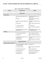
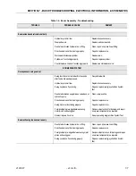
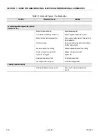
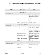
DRIVE SYSTEM.
No response to control.
Drive function not activated within 7 seconds
after footswitch was depressed.
Recycle footswitch.
Hydraulic system oil low.
Replenish oil as necessary.
Hydraulic pump not functioning properly.
Repair or replace pump.
Restricted or broken pump supply line.
Clean, repair or replace line.
Restricted or broken line on valve bank.
Clean, repair or replace line.
Air in wheel brake circuit.
Bleed circuit, determine and correct cause.
Damaged wiring on joystick.
Repair or replace wiring /Run System Test.
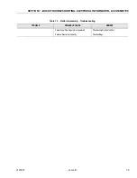
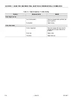
Table 7-4. Chassis Assembly - Troubleshooting
TROUBLE
PROBABLE CAUSE
REMEDY
Summary of Contents for JLG E400AJP
Page 2: ......
Page 32: ...SECTION 1 SPECIFICATIONS 1 18 JLG Lift 3121827 NOTES...
Page 42: ...SECTION 2 GENERAL 2 10 JLG Lift 3121827 NOTES...
Page 54: ...SECTION 3 CHASSIS TURNTABLE 3 12 JLG Lift 3121827 Figure 3 3 Speed Sensor Orientation...
Page 60: ...SECTION 3 CHASSIS TURNTABLE 3 18 JLG Lift 3121827 Figure 3 7 Steering Components and Spindles...
Page 62: ...SECTION 3 CHASSIS TURNTABLE 3 20 JLG Lift 3121827 Figure 3 9 Tilt Sensor Location...
Page 86: ...SECTION 3 CHASSIS TURNTABLE 3 44 JLG Lift 3121827 Figure 3 16 Swing Components...
Page 88: ...SECTION 3 CHASSIS TURNTABLE 3 46 JLG Lift 3121827 Figure 3 18 Battery Cable Connections...
Page 90: ...SECTION 3 CHASSIS TURNTABLE 3 48 JLG Lift 3121827 Figure 3 20 On Board Generator...
Page 97: ...SECTION 3 CHASSIS TURNTABLE 3121827 JLG Lift 3 55 Figure 3 22 Generator Components...
Page 116: ...SECTION 3 CHASSIS TURNTABLE 3 74 JLG Lift 3121827 NOTES...
Page 127: ...SECTION 4 BOOM PLATFORM 3121827 JLG Lift 4 11 Figure 4 10 Boom Limit Switches...
Page 140: ...SECTION 4 BOOM PLATFORM 4 24 JLG Lift 3121827 Figure 4 13 Rotator Counterbalance Valve...
Page 178: ...SECTION 5 HYDRAULICS 5 24 JLG Lift 3121827 Figure 5 26 HydraForce Cartridge Torque Value Chart...
Page 214: ...SECTION 6 JLG CONTROL SYSTEM 6 34 JLG Lift 3121827 NOTES...
Page 257: ......

