SECTION 7 - BASIC TROUBLESHOOTING, ELECTRICAL INFORMATION, & SCHEMATICS
7-12
– JLG Lift –
3121827
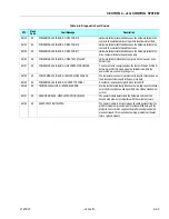
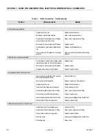
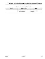
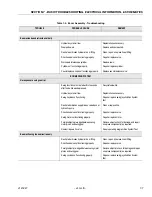
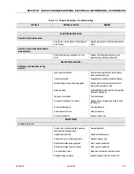
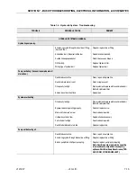
Joystick not functioning properly.
Replace joystick/Run System Test.
Charger plugged in.
Check help message.
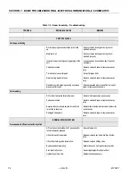
Drive prevented.
Check help message.
Brake(s) not releasing.
Determine cause and repair or replace.
Machine will not travel in forward.
Hydraulic system oil low.
Replenish oil as necessary.
Restricted or broken hydraulic line or fitting.
Clean, repair or replace line or fitting.
Motor turns slowly at maximum command.
Cutback - Tilted
Check help message.
Speed Sensor
Check help message.
Cutback - Elevation.
Check elevation switch.
Poor response, function shuts off slowly
when command is removed.
Ramp set too high in controller.
Check personality.
Sticking control handle.
Repair or replace controller.
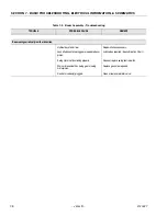
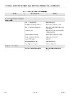
STEERING SYSTEM.
No response to steer control.
Hydraulic system pressure too low.
Adjust pressure.
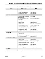
Damaged wiring on control switch or solenoid
valve.
Check wiring/Run System test.
Control switch not functioning properly.
Run system test.
Restricted or broken hydraulic line on valve
bank, hydraulic pump or rotary coupling. (If
equipped.)
Clean, repair or replace line.
Steer proportional flow valve not functioning
properly.
Run System Test.
Steer control valve not functioning properly.
Repair or replace valve.
Steer cylinder not functioning properly.
Repair or replace cylinder.
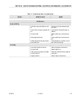
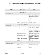
Machine hard to steer or steering is erratic
.
Hydraulic system oil low.
Replenish oil as necessary.
Restricted hydraulic line or fitting.
Clean, repair or replace line or fitting.
Steer system pressure low.
Adjust pressure.
Bent linkage (tie rods).
Repair or replace linkage as required.
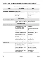
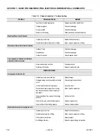
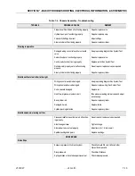
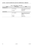
Table 7-4. Chassis Assembly - Troubleshooting
TROUBLE
PROBABLE CAUSE
REMEDY
Summary of Contents for JLG E400AJP
Page 2: ......
Page 32: ...SECTION 1 SPECIFICATIONS 1 18 JLG Lift 3121827 NOTES...
Page 42: ...SECTION 2 GENERAL 2 10 JLG Lift 3121827 NOTES...
Page 54: ...SECTION 3 CHASSIS TURNTABLE 3 12 JLG Lift 3121827 Figure 3 3 Speed Sensor Orientation...
Page 60: ...SECTION 3 CHASSIS TURNTABLE 3 18 JLG Lift 3121827 Figure 3 7 Steering Components and Spindles...
Page 62: ...SECTION 3 CHASSIS TURNTABLE 3 20 JLG Lift 3121827 Figure 3 9 Tilt Sensor Location...
Page 86: ...SECTION 3 CHASSIS TURNTABLE 3 44 JLG Lift 3121827 Figure 3 16 Swing Components...
Page 88: ...SECTION 3 CHASSIS TURNTABLE 3 46 JLG Lift 3121827 Figure 3 18 Battery Cable Connections...
Page 90: ...SECTION 3 CHASSIS TURNTABLE 3 48 JLG Lift 3121827 Figure 3 20 On Board Generator...
Page 97: ...SECTION 3 CHASSIS TURNTABLE 3121827 JLG Lift 3 55 Figure 3 22 Generator Components...
Page 116: ...SECTION 3 CHASSIS TURNTABLE 3 74 JLG Lift 3121827 NOTES...
Page 127: ...SECTION 4 BOOM PLATFORM 3121827 JLG Lift 4 11 Figure 4 10 Boom Limit Switches...
Page 140: ...SECTION 4 BOOM PLATFORM 4 24 JLG Lift 3121827 Figure 4 13 Rotator Counterbalance Valve...
Page 178: ...SECTION 5 HYDRAULICS 5 24 JLG Lift 3121827 Figure 5 26 HydraForce Cartridge Torque Value Chart...
Page 214: ...SECTION 6 JLG CONTROL SYSTEM 6 34 JLG Lift 3121827 NOTES...
Page 257: ......


