SECTION 2 - GENERAL
2-6
– JLG Lift –
3121827
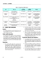
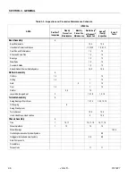
Table 2-3. Inspection and Preventive Maintenance Schedule
AREA
INTERVAL
Pre-Start
1
Inspection
Weekly
Preventive
Maintenance
Monthly
Preventive
Maintenance
Pre-Delivery
2
or Frequent
3
Inspection
Annual
4
(Yearly)
Inspection
Every 2
Years
Boom Assembly
9
Boom Weldments
1,2,4
1,2,4
Hose/Cable Carrier Installations
1,2,9,12
1,2,9,12
Pivot Pins and Pin Retainers
1,2
1,2
Sheaves, Sheave Pins
1,2
1,2
Bearings
1,2
1,2
Wear Pads
1,2
1,2
Covers or Shields
1,2
1,2
Extend/Retract Chain or Cable Systems
1,2,3
1,2,3
Platform Assembly
9
Platform
1,2
1,2
Railing
1,2
1
1,2
Gate
5
1
1,5
Floor
1,2
1
1,2
Rotator
9,5
15
Lanyard Anchorage Point
2
1,2,10
1,2,10
Turntable Assembly
9
Swing Bearing or Worm Gear
1,2,14
1,2,3,13,14
Oil Coupling
9
Swing Drive System
Turntable Lock
1,2,5
1,2,5
Hood, Hood Props, Hood Latches
5
1,2,5
Chassis Assembly
9
Tires
1
16,17
16,17,18
16,17,18
Wheel Nuts/Bolts
1
15
15
15
Wheel Bearings
14,24
Oscillating Axle/Lockout Cylinder Systems
5,8
Outrigger or Extendable Axle Systems
5,8
5,8
Steer Components
Drive Motors
Torque Hubs
11
11
Summary of Contents for JLG E400AJP
Page 2: ......
Page 32: ...SECTION 1 SPECIFICATIONS 1 18 JLG Lift 3121827 NOTES...
Page 42: ...SECTION 2 GENERAL 2 10 JLG Lift 3121827 NOTES...
Page 54: ...SECTION 3 CHASSIS TURNTABLE 3 12 JLG Lift 3121827 Figure 3 3 Speed Sensor Orientation...
Page 60: ...SECTION 3 CHASSIS TURNTABLE 3 18 JLG Lift 3121827 Figure 3 7 Steering Components and Spindles...
Page 62: ...SECTION 3 CHASSIS TURNTABLE 3 20 JLG Lift 3121827 Figure 3 9 Tilt Sensor Location...
Page 86: ...SECTION 3 CHASSIS TURNTABLE 3 44 JLG Lift 3121827 Figure 3 16 Swing Components...
Page 88: ...SECTION 3 CHASSIS TURNTABLE 3 46 JLG Lift 3121827 Figure 3 18 Battery Cable Connections...
Page 90: ...SECTION 3 CHASSIS TURNTABLE 3 48 JLG Lift 3121827 Figure 3 20 On Board Generator...
Page 97: ...SECTION 3 CHASSIS TURNTABLE 3121827 JLG Lift 3 55 Figure 3 22 Generator Components...
Page 116: ...SECTION 3 CHASSIS TURNTABLE 3 74 JLG Lift 3121827 NOTES...
Page 127: ...SECTION 4 BOOM PLATFORM 3121827 JLG Lift 4 11 Figure 4 10 Boom Limit Switches...
Page 140: ...SECTION 4 BOOM PLATFORM 4 24 JLG Lift 3121827 Figure 4 13 Rotator Counterbalance Valve...
Page 178: ...SECTION 5 HYDRAULICS 5 24 JLG Lift 3121827 Figure 5 26 HydraForce Cartridge Torque Value Chart...
Page 214: ...SECTION 6 JLG CONTROL SYSTEM 6 34 JLG Lift 3121827 NOTES...
Page 257: ......

