SECTION 3 - CHASSIS & TURNTABLE
3-10
– JLG Lift –
3121827
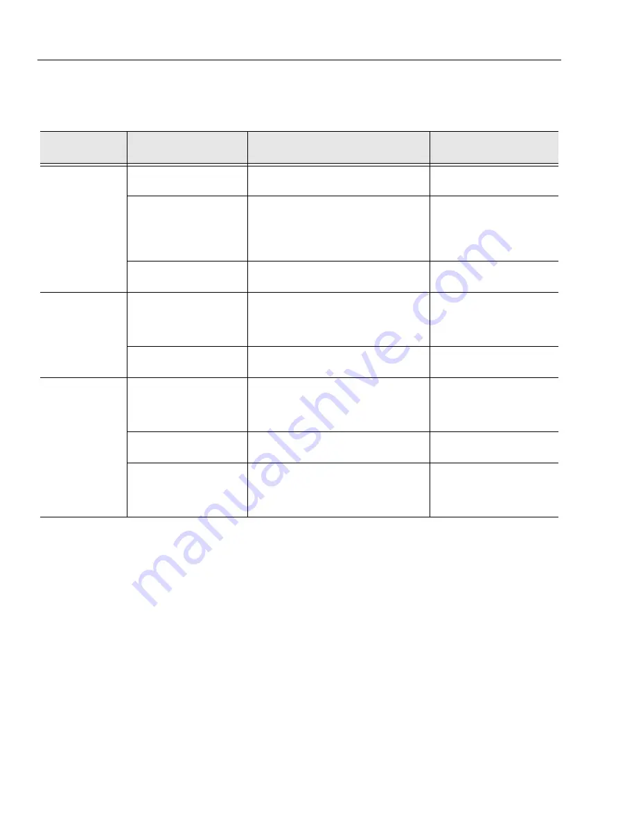
Table 3-2. Drive Brake Diagnosis
Problem
Cause
Explanation
Corrective
Action
Brake slips
Excessive pressure In hydraulic
system
If there is back pressure in the actuation line of the
brake, holding torque will be reduced.
Check filters. hose size, restrictions
in other hydraulic components.
Oil In brake if designed for dry
use
Wet linings generate 67% of the dry torque rating. If
the brake has oil In it, check the type of oil hydraulic
or gearbox.
1. Gearbox oil
2. Hydraulic oil
Replace oil seal in brake. Check
motor seal. Check piston seals.
Note: Internal components will
need to be inspected, cleaned, and
replaced as required.
Springs broken or have taken a
permanent set
Broken or set springs can cause reduced torque -
rare occurrence.
See spring replacement
Brake drags or runs
hot
Low actuation pressure
The brake should be pressurized to minimum of
1.38 bar (20 psi) over the full release pressure under
normal operating conditions. Lower pressures will
cause the brake to drag thus generating heat.
Place pressure gauge in bleed port
& check pressure with system on.
Bearing failure
If the bearing should fall. a large amount of drag can
be generated.
Replace bearing.
Brake will not release
Stuck or clogged valve
Brakes are designed to come on when system pres-
sure drops below stated release pressure. If pres-
sure cannot get to brake, the brake will not release.
Place pressure gauge in bleed port
- check for adequate pressure.
Replace defective line or compo-
nent.
Bad o-rings
Release piston will not hold pressure, brake will not
release.
Replace o-rings.
Discs frozen
These brakes are designed for only limited dynamic
braking. A severe emergency stop or prolonged
reduced release pressure operation may result in
this type of damage.
Replace disc stack.
Summary of Contents for JLG E400AJP
Page 2: ......
Page 32: ...SECTION 1 SPECIFICATIONS 1 18 JLG Lift 3121827 NOTES...
Page 42: ...SECTION 2 GENERAL 2 10 JLG Lift 3121827 NOTES...
Page 54: ...SECTION 3 CHASSIS TURNTABLE 3 12 JLG Lift 3121827 Figure 3 3 Speed Sensor Orientation...
Page 60: ...SECTION 3 CHASSIS TURNTABLE 3 18 JLG Lift 3121827 Figure 3 7 Steering Components and Spindles...
Page 62: ...SECTION 3 CHASSIS TURNTABLE 3 20 JLG Lift 3121827 Figure 3 9 Tilt Sensor Location...
Page 86: ...SECTION 3 CHASSIS TURNTABLE 3 44 JLG Lift 3121827 Figure 3 16 Swing Components...
Page 88: ...SECTION 3 CHASSIS TURNTABLE 3 46 JLG Lift 3121827 Figure 3 18 Battery Cable Connections...
Page 90: ...SECTION 3 CHASSIS TURNTABLE 3 48 JLG Lift 3121827 Figure 3 20 On Board Generator...
Page 97: ...SECTION 3 CHASSIS TURNTABLE 3121827 JLG Lift 3 55 Figure 3 22 Generator Components...
Page 116: ...SECTION 3 CHASSIS TURNTABLE 3 74 JLG Lift 3121827 NOTES...
Page 127: ...SECTION 4 BOOM PLATFORM 3121827 JLG Lift 4 11 Figure 4 10 Boom Limit Switches...
Page 140: ...SECTION 4 BOOM PLATFORM 4 24 JLG Lift 3121827 Figure 4 13 Rotator Counterbalance Valve...
Page 178: ...SECTION 5 HYDRAULICS 5 24 JLG Lift 3121827 Figure 5 26 HydraForce Cartridge Torque Value Chart...
Page 214: ...SECTION 6 JLG CONTROL SYSTEM 6 34 JLG Lift 3121827 NOTES...
Page 257: ......


