SECTION 3 - CHASSIS & TURNTABLE
3121827
– JLG Lift –
3-47
Battery Charging (On Board Charger)
1.
For maximum battery life:
a.
Avoid completely discharging the batteries.
b.
Fully charge the batteries each day the machine
is used.
c.
Charge the batteries at available times between
charging.
d.
Be sure the battery fluid covers the battery
plates before charging, but to avoid overflow, do
not top off the fluid level until charging.
2.
To charge the batteries, connect the charger to a
115 volt source with a 15 amp minimum capacity.
3.
The Charger will shut off automatically when the bat-
teries are fully charged.
4.
The charge cycle is complete when the ammeter
reads 0 amps. Any reading indicates the charge
cycle is not complete.
5.
Depleted batteries will take approximately 17 hours
to charge.
Optional On Board Generator
EXHAUST GAS HAZARD. RUN THE GENERATOR IN A WELL VENTI-
LATED AREA ONLY.
WHEN THE GENERATOR ENABLE CONTROL LOCATED IN THE
PLATFORM CONTROL BOX IS IN THE ON POSITION AND THE
GROUND EMERGENCY STOP SWITCH IS ON (PULLED OUT), THE
GENERATOR WILL START AUTOMATICALLY WHEN THE BATTER-
IES REACH A LOW-CHARGE STATE, AUTOMATICALLY CHARGING
THE BATTERIES. THE GENERATOR WILL ALSO AUTOMATICALLY
START IF THE GENERATOR START BATTERY IS LOW.
NOTE:
The engine will automatically shut down under the
following conditions:
High Engine Oil Temperature
Low Engine Oil Pressure
Engine Overspeed
Generator Over voltage
Batteries fully charged
Engine underspeed
TO AVOID INJURY FROM AN EXPLOSION, DO NOT SMOKE OR
ALLOW SPARKS OR A FLAME NEAR BATTERY DURING SERVIC-
ING. ALWAYS WEAR EYE AND HAND PROTECTION WHEN SER-
VICING BATTERIES.
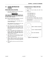
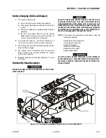
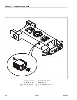
Figure 3-19. Batteries and Battery Charger (Prior to S/N 0300059350)
Summary of Contents for JLG E400AJP
Page 2: ......
Page 32: ...SECTION 1 SPECIFICATIONS 1 18 JLG Lift 3121827 NOTES...
Page 42: ...SECTION 2 GENERAL 2 10 JLG Lift 3121827 NOTES...
Page 54: ...SECTION 3 CHASSIS TURNTABLE 3 12 JLG Lift 3121827 Figure 3 3 Speed Sensor Orientation...
Page 60: ...SECTION 3 CHASSIS TURNTABLE 3 18 JLG Lift 3121827 Figure 3 7 Steering Components and Spindles...
Page 62: ...SECTION 3 CHASSIS TURNTABLE 3 20 JLG Lift 3121827 Figure 3 9 Tilt Sensor Location...
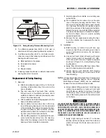
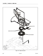
Page 86: ...SECTION 3 CHASSIS TURNTABLE 3 44 JLG Lift 3121827 Figure 3 16 Swing Components...
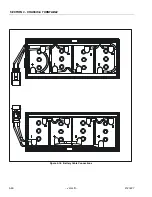
Page 88: ...SECTION 3 CHASSIS TURNTABLE 3 46 JLG Lift 3121827 Figure 3 18 Battery Cable Connections...
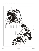
Page 90: ...SECTION 3 CHASSIS TURNTABLE 3 48 JLG Lift 3121827 Figure 3 20 On Board Generator...
Page 97: ...SECTION 3 CHASSIS TURNTABLE 3121827 JLG Lift 3 55 Figure 3 22 Generator Components...
Page 116: ...SECTION 3 CHASSIS TURNTABLE 3 74 JLG Lift 3121827 NOTES...
Page 127: ...SECTION 4 BOOM PLATFORM 3121827 JLG Lift 4 11 Figure 4 10 Boom Limit Switches...
Page 140: ...SECTION 4 BOOM PLATFORM 4 24 JLG Lift 3121827 Figure 4 13 Rotator Counterbalance Valve...
Page 178: ...SECTION 5 HYDRAULICS 5 24 JLG Lift 3121827 Figure 5 26 HydraForce Cartridge Torque Value Chart...
Page 214: ...SECTION 6 JLG CONTROL SYSTEM 6 34 JLG Lift 3121827 NOTES...
Page 257: ......

