SECTION 4 - BOOM & PLATFORM
4-8
– JLG Lift –
3121827
4.8 BOOM SYNCHRONIZING PROCEDURE
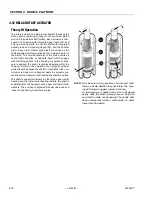
NOTE:
If the Lower Boom assembly does not fully lower:
1.
Remove all personnel from the platform.
2.
Pull the red knob located under the main control
valve.
3.
From Ground Control, activate the lift control switch,
raise Lower Boom 6 feet (1.8m).
4.
After raising Lower Boom, release the red knob.
5.
Activate Lower Boom Down, fully lower boom.
6.
Repeat step 1 thru 5 if necessary.
4.9 ARTICULATING JIB BOOM
Removal
1.
For platform/support removal see platform/support
removal diagram. See Section 4.1, Boom Mainte-
nance.
2.
Position the articulating jib boom level with ground.
3.
Remove mounting hardware from slave leveling cyl-
inder pin #1. Using a suitable brass drift and ham-
mer, remove the cylinder pin from articulating jib
boom.
4.
Remove mounting hardware from articulating jib
boom pivot pin #2. Using a suitable brass drift and
hammer, remove the pivot pin from boom assembly.
Disassembly
1.
Remove mounting hardware from articulating jib
boom pivot pins #3 and #4. Using a suitable brass
drift and hammer, remove the pins from articulating
jib boom pivot weldment.
2.
Remove mounting hardware from rotator support
and jib lift cylinder pins #5 and #6. Using a suitable
brass drift and hammer, remove the pins from rotator
support.
Inspection
1.
.Inspect articulating fly boom pivot pin for wear,
scoring, tapering and ovality, or other damage.
Replace pins as necessary.
2.
Inspect articulating fly boom pivot attach points for
scoring, tapering and ovality, or other damage.
Replace pins as necessary.
3.
Inspect inner diameter of articulating fly boom pivot
bearings for scoring, distortion, wear, or other dam-
age. Replace bearings as necessary. (See Cylinder
repair For Bearing Replacement).
4.
Inspect lift cylinder attach pin for wear, scoring,
tapering and ovality, or other damage. Ensure pin
surfaces are protected prior to installation. Replace
pins as necessary.
5.
Inspect inner diameter of rotator attach point bear-
ings for scoring, distortion, wear, or other damage.
Replace bearing as necessary. (See Cylinder repair
For Bearing Replacement).
6.
Inspect all threaded components for damage such
as stretching, thread deformation, or twisting.
Replace as necessary.
7.
Inspect structural units of articulating jib boom
assembly for bending, cracking, separation of
welds, or other damage. Replace boom sections as
necessary.
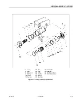
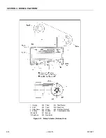
Figure 4-7. Location of Components - Articulating
Jib Boom
Summary of Contents for JLG E400AJP
Page 2: ......
Page 32: ...SECTION 1 SPECIFICATIONS 1 18 JLG Lift 3121827 NOTES...
Page 42: ...SECTION 2 GENERAL 2 10 JLG Lift 3121827 NOTES...
Page 54: ...SECTION 3 CHASSIS TURNTABLE 3 12 JLG Lift 3121827 Figure 3 3 Speed Sensor Orientation...
Page 60: ...SECTION 3 CHASSIS TURNTABLE 3 18 JLG Lift 3121827 Figure 3 7 Steering Components and Spindles...
Page 62: ...SECTION 3 CHASSIS TURNTABLE 3 20 JLG Lift 3121827 Figure 3 9 Tilt Sensor Location...
Page 86: ...SECTION 3 CHASSIS TURNTABLE 3 44 JLG Lift 3121827 Figure 3 16 Swing Components...
Page 88: ...SECTION 3 CHASSIS TURNTABLE 3 46 JLG Lift 3121827 Figure 3 18 Battery Cable Connections...
Page 90: ...SECTION 3 CHASSIS TURNTABLE 3 48 JLG Lift 3121827 Figure 3 20 On Board Generator...
Page 97: ...SECTION 3 CHASSIS TURNTABLE 3121827 JLG Lift 3 55 Figure 3 22 Generator Components...
Page 116: ...SECTION 3 CHASSIS TURNTABLE 3 74 JLG Lift 3121827 NOTES...
Page 127: ...SECTION 4 BOOM PLATFORM 3121827 JLG Lift 4 11 Figure 4 10 Boom Limit Switches...
Page 140: ...SECTION 4 BOOM PLATFORM 4 24 JLG Lift 3121827 Figure 4 13 Rotator Counterbalance Valve...
Page 178: ...SECTION 5 HYDRAULICS 5 24 JLG Lift 3121827 Figure 5 26 HydraForce Cartridge Torque Value Chart...
Page 214: ...SECTION 6 JLG CONTROL SYSTEM 6 34 JLG Lift 3121827 NOTES...
Page 257: ......


