SECTION 1 - SPECIFICATIONS
1-4
– JLG Lift –
3121827
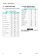
1.11 CYLINDER SPECIFICATIONS
NOTE:
All dimensions are given in inches (in.), with the met-
ric equivalent, millimeters (mm), given in parenthe-
ses.
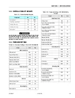
1.12 MAJOR COMPONENT WEIGHTS
SELECT LIFTING EQUIPMENT WITH CAPACITY CAPABLE OF
SAFELY SUPPORTING WEIGHT.
Table 1-11. Cylinder Specifications
Cylinder
Bore
Stroke
Rod Dia.
Upper Lift Cylinder
3.00
(76.2)
28.3125
(719.1)
1.50
(38.1)
Mid Lift Cylinder
3.00
(76.2)
21.25
(539.7)
1.50
(38.1)
Lower Lift Cylinder
4.00
(101.6)
23.25
(590.5)
2.25
(57.1)
Telescope Cylinder
2.00
(50.8)
92
(2337)
1.25
(31.8)
Master Cylinder (E/M400A)
2.00
(50.8)
9.375
(238.1)
1.00
(25.4)
Master Cylinder (E/M400AJP)
3.00
(75)
11.5
(292)
1.25
(32)
Slave Cylinder (E/M400A)
2.00
(50.8)
9.375
(238.1)
1.00
(25.4)
Slave Cylinder (E/M400AJP)
3.00
(75)
11.6
(295.5)
1.25
(32)
Rotator Cylinder
1.875
(47.6)
15.250
(387.3)
1.00
(25.4)
Steer Cylinder (Double Rod)
2.50
(63.5)
4.06
(103.1)
1.75
(44.5)
Jib Cylinder
63.5
(2.5)
233.6
(9.2)
44.5
(1.75)
Table 1-12.Major Component Weights
Component
LB.
KG.
Platform and Support
215
97.5
Upper Boom Complete
810
367
Mid Boom Complete
550
249
Lower Boom Complete
550
249
Upper Lift Cylinder
89
40
Mid Lift Cylinder
95
43
Lower Lift Cylinder
110
50
Telescope Cylinder
85
38.5
Upper Upright
225
102
Lower Upright
97
44
Turntable
948
430
Battery Box (incl. batteries)
600
272
Chassis (w/ pneu. tires)
4,295
1948
Chassis (w/ foam-filled tires)
4,695
2130
Counterweight
3850
1746
Machine Complete
11,800
5352
Jib
320
145
Summary of Contents for JLG E400AJP
Page 2: ......
Page 32: ...SECTION 1 SPECIFICATIONS 1 18 JLG Lift 3121827 NOTES...
Page 42: ...SECTION 2 GENERAL 2 10 JLG Lift 3121827 NOTES...
Page 54: ...SECTION 3 CHASSIS TURNTABLE 3 12 JLG Lift 3121827 Figure 3 3 Speed Sensor Orientation...
Page 60: ...SECTION 3 CHASSIS TURNTABLE 3 18 JLG Lift 3121827 Figure 3 7 Steering Components and Spindles...
Page 62: ...SECTION 3 CHASSIS TURNTABLE 3 20 JLG Lift 3121827 Figure 3 9 Tilt Sensor Location...
Page 86: ...SECTION 3 CHASSIS TURNTABLE 3 44 JLG Lift 3121827 Figure 3 16 Swing Components...
Page 88: ...SECTION 3 CHASSIS TURNTABLE 3 46 JLG Lift 3121827 Figure 3 18 Battery Cable Connections...
Page 90: ...SECTION 3 CHASSIS TURNTABLE 3 48 JLG Lift 3121827 Figure 3 20 On Board Generator...
Page 97: ...SECTION 3 CHASSIS TURNTABLE 3121827 JLG Lift 3 55 Figure 3 22 Generator Components...
Page 116: ...SECTION 3 CHASSIS TURNTABLE 3 74 JLG Lift 3121827 NOTES...
Page 127: ...SECTION 4 BOOM PLATFORM 3121827 JLG Lift 4 11 Figure 4 10 Boom Limit Switches...
Page 140: ...SECTION 4 BOOM PLATFORM 4 24 JLG Lift 3121827 Figure 4 13 Rotator Counterbalance Valve...
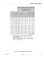
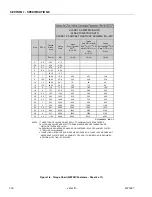
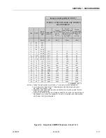
Page 178: ...SECTION 5 HYDRAULICS 5 24 JLG Lift 3121827 Figure 5 26 HydraForce Cartridge Torque Value Chart...
Page 214: ...SECTION 6 JLG CONTROL SYSTEM 6 34 JLG Lift 3121827 NOTES...
Page 257: ......


