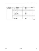
SECTION 6 - JLG CONTROL SYSTEM
6-10
– JLG Lift –
3121827
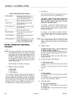
Machine Configuration Programming
Information
4150286-9
NOTE:
The following information is to be used when working
with the MACHINE SETUP menu. When configuring
the machine, the machine configuration must be
completed before any personality settings can be
changed. Changing the personality settings first and
then changing the model number of the machine
configuration will cause the personality settings to
return to default values.
Default settings will be shown in bold type.
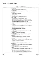
1.
MODELS (names may change)
1=Model E300
2=Model 400*
3 = Model 45/450*
* The elevated drive speed setting must be changed to
10% for E45AJ, M45AJ, M40AJP, E40AJP, M450AJ,
E450AJ, M400AJP, E400AJP, E400A , and M400A
machines going to Europe (CE). Also the elevated drive
speed setting must be changed to 15% for E40AJPn,
M40APn, E400AJP narrow, M400AJPn, E400A narrow,
and M400A narrow machines going to Europe (CE).
1.
TILT SWITCH
When tilted the tilt light is lit (continuously) and drive
speed is reduced to the creep speed setting
1=5 degree - reduces the maximum speed of all
platform functions to creep when tilted and
above elevation. Reduces drive speed to creep
when tilted. (Domestic/Japan)
2=3 degree - reduces the maximum speed of all
platform functions to creep when tilted and above
elevation. Reduces drive speed to creep when tilted.
(European/Australian)
3=3 degree - cuts out drive and reduces functions
to creep speed when tilted and above elevation.
Reduces drive speed to creep when tilted only.
(Option)
NOTE:
Any of the selections above will light the tilt lamp
when a tilted condition occurs and will sound the
platform alarm when the machine is tilted and above
elevation.
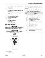
2.
DRIVE CUTOUT
0=Battery Charger Cutout - cuts out drive when
the battery charger is plugged in
1= Battery Charger Cutout and Simultaneous Drive
and Boom functions disabled above elevation (Euro-
pean/Australian)
2= Battery Charger Cutout and Drive Cutout above
elevation (Option)
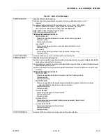
3.
FUNCTION CUTOUT LIMIT SWITCH
0= No Function Cutout
1= Cuts out all boom functions when switch opens
(Option)
2= Cuts out all functions when the switch opens
(Option)
4.
JIB
0=No jib installed
1=Jib installed which has up and down movements
only (Option)
2=Jib installed which has up and down movements
and side to side movements (Option)
5.
GROUND ALARM
0= No ground alarm installed
1= Travel Alarm - Sounds when the drive function is
active (Option)
2= Descent Alarm - Sounds when either lift down is
active (Option)
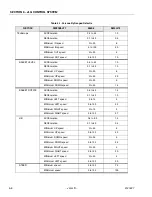
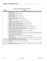
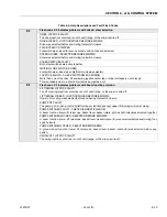
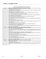
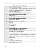
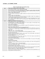
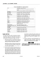
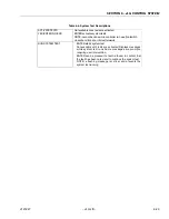
Table 6-2. Machine Setup Descriptions
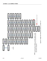
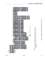
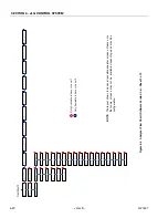
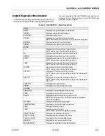
MODEL NUMBER...
Displays/adjusts machine model
NOTE: all personalities reset to default
when model number is altered
TILT...
Displays/adjusts tilt sensor function
DRIVE CUTOUT...
Displays/adjusts drive cutout switch
presence/ function
FUNCTION CUTOUT...
Displays/adjusts function cutout switch
presence/function
JIB...
Displays/adjusts jib presence
GROUND ALARM...
Displays/adjusts ground alarm pres-
ence/ function
PLATFORM ALARM...
Displays/adjusts platform alarm pres-
ence/ function
BATTERY MONITOR...
Displays/adjusts battery monitor, which
indicates “WATER BATTERIES” after a
number of charge/discharge cycles
Summary of Contents for JLG E400AJP
Page 2: ......
Page 32: ...SECTION 1 SPECIFICATIONS 1 18 JLG Lift 3121827 NOTES...
Page 42: ...SECTION 2 GENERAL 2 10 JLG Lift 3121827 NOTES...
Page 54: ...SECTION 3 CHASSIS TURNTABLE 3 12 JLG Lift 3121827 Figure 3 3 Speed Sensor Orientation...
Page 60: ...SECTION 3 CHASSIS TURNTABLE 3 18 JLG Lift 3121827 Figure 3 7 Steering Components and Spindles...
Page 62: ...SECTION 3 CHASSIS TURNTABLE 3 20 JLG Lift 3121827 Figure 3 9 Tilt Sensor Location...
Page 86: ...SECTION 3 CHASSIS TURNTABLE 3 44 JLG Lift 3121827 Figure 3 16 Swing Components...
Page 88: ...SECTION 3 CHASSIS TURNTABLE 3 46 JLG Lift 3121827 Figure 3 18 Battery Cable Connections...
Page 90: ...SECTION 3 CHASSIS TURNTABLE 3 48 JLG Lift 3121827 Figure 3 20 On Board Generator...
Page 97: ...SECTION 3 CHASSIS TURNTABLE 3121827 JLG Lift 3 55 Figure 3 22 Generator Components...
Page 116: ...SECTION 3 CHASSIS TURNTABLE 3 74 JLG Lift 3121827 NOTES...
Page 127: ...SECTION 4 BOOM PLATFORM 3121827 JLG Lift 4 11 Figure 4 10 Boom Limit Switches...
Page 140: ...SECTION 4 BOOM PLATFORM 4 24 JLG Lift 3121827 Figure 4 13 Rotator Counterbalance Valve...
Page 178: ...SECTION 5 HYDRAULICS 5 24 JLG Lift 3121827 Figure 5 26 HydraForce Cartridge Torque Value Chart...
Page 214: ...SECTION 6 JLG CONTROL SYSTEM 6 34 JLG Lift 3121827 NOTES...
Page 257: ......

