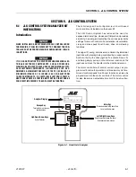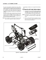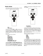
SECTION 6 - JLG CONTROL SYSTEM
3121827
– JLG Lift –
6-11
3= Motion Alarm - Sounds when any function is
active (Option)
6.
PLATFORM ALARM
0= Sounds continuously when above elevation
and tilted only.
1= Sounds continuously when above elevation and
tilted, and in conjunction with fault code flashes
(Option)
7.
SOFT TOUCH
0=No Soft Touch System Installed
1= Soft-Touch System Installed
8.
LOAD CELL
0=No Load Cell Installed
1= Warn Only
2 = Warn & Cutout
3 = Warn & Boom Cutout
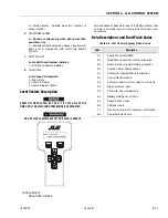
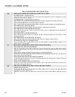
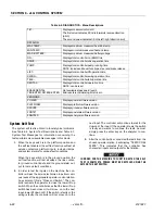
Level Vehicle Description
A NEW TILT MODULE WILL ACT AS IF IT IS TILTED ALL OF THE
TIME UNTIL THE FOLLOWING PROCEDURE IS PERFORMED.
DO NOT LEVEL VEHICLE EXCEPT ON A LEVEL SURFACE.
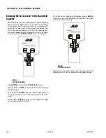
LEVEL VEHICLE
YES:ENTER, NO:ESC
Not available at password level 2 ENTER confirms that
vehicle is currently level, and zeroes the tilt sensor mea-
surements
Help Descriptions and Fault Flash Codes
LEVEL VEHICLE
YES:ENTER, NO:ESC
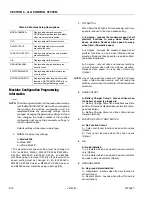
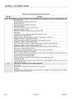
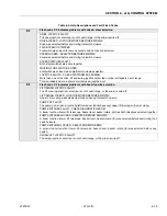
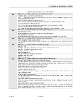
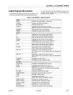
Table 6-3. JLG Control System Flash Codes
Code
Description
2-1
2-2
2-3
2-5
3-1
3-2
3-3
3-5
4-2
4-4
5-5
6-6
7-7
9-9
Faulty Foot switch/EMS
Drive/Steer inputs/Foot switch Interlocks
Boom function inputs/Lift-Swing Joystick
Function Cutout/Drive Cutout
Contactors miswired/Motors miswired
Line contactor welded
Contactor short circuit or valve short circuit
Brake pressure input
Controller Over temperature
Battery voltage out of range
Speed Sensor input
CANbus inputs
Traction /Pump motor wiring or motor faulty
Power Module Failure
Summary of Contents for JLG E400AJP
Page 2: ......
Page 32: ...SECTION 1 SPECIFICATIONS 1 18 JLG Lift 3121827 NOTES...
Page 42: ...SECTION 2 GENERAL 2 10 JLG Lift 3121827 NOTES...
Page 54: ...SECTION 3 CHASSIS TURNTABLE 3 12 JLG Lift 3121827 Figure 3 3 Speed Sensor Orientation...
Page 60: ...SECTION 3 CHASSIS TURNTABLE 3 18 JLG Lift 3121827 Figure 3 7 Steering Components and Spindles...
Page 62: ...SECTION 3 CHASSIS TURNTABLE 3 20 JLG Lift 3121827 Figure 3 9 Tilt Sensor Location...
Page 86: ...SECTION 3 CHASSIS TURNTABLE 3 44 JLG Lift 3121827 Figure 3 16 Swing Components...
Page 88: ...SECTION 3 CHASSIS TURNTABLE 3 46 JLG Lift 3121827 Figure 3 18 Battery Cable Connections...
Page 90: ...SECTION 3 CHASSIS TURNTABLE 3 48 JLG Lift 3121827 Figure 3 20 On Board Generator...
Page 97: ...SECTION 3 CHASSIS TURNTABLE 3121827 JLG Lift 3 55 Figure 3 22 Generator Components...
Page 116: ...SECTION 3 CHASSIS TURNTABLE 3 74 JLG Lift 3121827 NOTES...
Page 127: ...SECTION 4 BOOM PLATFORM 3121827 JLG Lift 4 11 Figure 4 10 Boom Limit Switches...
Page 140: ...SECTION 4 BOOM PLATFORM 4 24 JLG Lift 3121827 Figure 4 13 Rotator Counterbalance Valve...
Page 178: ...SECTION 5 HYDRAULICS 5 24 JLG Lift 3121827 Figure 5 26 HydraForce Cartridge Torque Value Chart...
Page 214: ...SECTION 6 JLG CONTROL SYSTEM 6 34 JLG Lift 3121827 NOTES...
Page 257: ......

