SECTION 7 - BASIC TROUBLESHOOTING, ELECTRICAL INFORMATION, & SCHEMATICS
7-28
– JLG Lift –
3121827
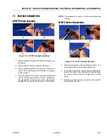
HD30/HDP20 Series Assembly
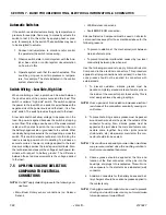
1. Grasp contact about 25mm behind the contact
crimp barrel.
2. Hold connector with rear grommet facing you.
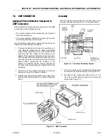
3. Push contact straight into connector grommet until a
positive stop is felt. A slight tug will confirm that it is
properly locked in place.
NOTE:
For unused wire cavities, insert sealing plugs for full
environmental sealing
HD30/HDP20 Series Disassembly
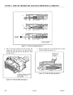
1. With rear insert toward you, snap appropriate size
extractor tool over the wire of contact to be
removed.
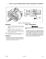
2. Slide tool along into the insert cavity until it engages
contact and resistance is felt.
3. Pull contact-wire assembly out of connector.
NOTE:
Do Not twist or insert tool at an angle.
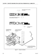
Figure 7-14. HD/HDP Contact Installation
A
B
C
Figure 7-15. HD/HDP Locking Contacts Into Position
Figure 7-16. HD/HDP Contact Removal
A
B
C
Figure 7-17. HD/HDP Unlocking Contacts
Summary of Contents for JLG E400AJP
Page 2: ......
Page 32: ...SECTION 1 SPECIFICATIONS 1 18 JLG Lift 3121827 NOTES...
Page 42: ...SECTION 2 GENERAL 2 10 JLG Lift 3121827 NOTES...
Page 54: ...SECTION 3 CHASSIS TURNTABLE 3 12 JLG Lift 3121827 Figure 3 3 Speed Sensor Orientation...
Page 60: ...SECTION 3 CHASSIS TURNTABLE 3 18 JLG Lift 3121827 Figure 3 7 Steering Components and Spindles...
Page 62: ...SECTION 3 CHASSIS TURNTABLE 3 20 JLG Lift 3121827 Figure 3 9 Tilt Sensor Location...
Page 86: ...SECTION 3 CHASSIS TURNTABLE 3 44 JLG Lift 3121827 Figure 3 16 Swing Components...
Page 88: ...SECTION 3 CHASSIS TURNTABLE 3 46 JLG Lift 3121827 Figure 3 18 Battery Cable Connections...
Page 90: ...SECTION 3 CHASSIS TURNTABLE 3 48 JLG Lift 3121827 Figure 3 20 On Board Generator...
Page 97: ...SECTION 3 CHASSIS TURNTABLE 3121827 JLG Lift 3 55 Figure 3 22 Generator Components...
Page 116: ...SECTION 3 CHASSIS TURNTABLE 3 74 JLG Lift 3121827 NOTES...
Page 127: ...SECTION 4 BOOM PLATFORM 3121827 JLG Lift 4 11 Figure 4 10 Boom Limit Switches...
Page 140: ...SECTION 4 BOOM PLATFORM 4 24 JLG Lift 3121827 Figure 4 13 Rotator Counterbalance Valve...
Page 178: ...SECTION 5 HYDRAULICS 5 24 JLG Lift 3121827 Figure 5 26 HydraForce Cartridge Torque Value Chart...
Page 214: ...SECTION 6 JLG CONTROL SYSTEM 6 34 JLG Lift 3121827 NOTES...
Page 257: ......

