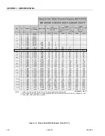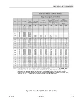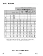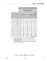
SECTION 2 - GENERAL
2-4
– JLG Lift –
3121827
fied intervals required in the Lubrication Chart in
Section 1. Always examine filters for evidence of
metal particles.
3.
Cloudy oils indicate a high moisture content which
permits organic growth, resulting in oxidation or cor-
rosion. If this condition occurs, the system must be
drained, flushed, and refilled with clean oil.
4.
It is not advisable to mix oils of different brands or
types, as they may not contain the same required
additives or be of comparable viscosities. Good
grade mineral oils, with viscosities suited to the
ambient temperatures in which the machine is oper-
ating, are recommended for use.
NOTE:
Metal particles may appear in the oil or filters of new
machines due to the wear-in of meshing compo-
nents.
Hydraulic Oil
1.
Refer to Section 1 for recommendations for viscosity
ranges.
2.
JLG recommends Mobil DTE-11 hydraulic oil, which
has an SAE viscosity of 10W and a viscosity index of
140.
NOTE:
Start-up of hydraulic system with oil temperatures
below -20 degrees F (-29 degrees C) is not recom-
mended. If it is necessary to start the system in a
sub-zero environment, it will be necessary to heat
the oil with a low density, 100VAC heater to a mini-
mum temperature of -20 degrees F (-29 degrees C).
Changing Hydraulic Oil
1.
Filter elements must be changed after the first 50
hours of operation and every 300 hours thereafter. If
it is necessary to change the oil, use only those oils
meeting or exceeding the specifications appearing
in this manual. If unable to obtain the same type of
oil supplied with the machine, consult local supplier
for assistance in selecting the proper equivalent.
Avoid mixing petroleum and synthetic base oils.
2.
Use every precaution to keep the hydraulic oil clean.
If the oil must be poured from the original container
into another, be sure to clean all possible contami-
nants from the service container. Always clean the
mesh element of the filter and replace the cartridge
any time the system oil is changed.
3.
While the unit is shut down, a good preventive main-
tenance measure is to make a thorough inspection
of all hydraulic components, lines, fittings, etc., as
well as a functional check of each system, before
placing the machine back in service.
Lubrication Specifications
Specified lubricants, as recommended by the component
manufacturers, are always the best choice, however,
multi-purpose greases usually have the qualities which
meet a variety of single purpose grease requirements.
Should any question arise, regarding the use of greases in
maintenance stock, consult your local supplier for evalua-
tion. Refer to Section 1 for an explanation of the lubricant
key designations appearing in the Lubrication Chart.
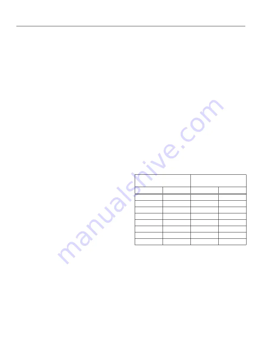
2.4 CYLINDER DRIFT TEST
Maximum acceptable cylinder drift is to be measured
using the following methods.
Platform Drift
Measure the drift of the platform to the ground. Lower
booms (if equipped) slightly elevated, upper boom fully
extended with the rated load in the platform and power off.
Maximum allowable drift is 2 inches (5 cm) in 10 minutes.
If the machine does not pass this test, proceed with the
following.
Cylinder Drift
Drift is to be measured at the cylinder rod with a calibrated
dial indicator. The cylinder oil must be at ambient temper-
ature and temperature stabilized.
The cylinder must have the normal load, which is the nor-
mal platform load applied.
If the cylinder passes this test, it is acceptable.
NOTE:
This information is based on 6 drops per minute cyl-
inder leakage.
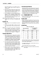
Table 2-2. Cylinder Drift
Cylinder Bore Diameter
Max. Acceptable Drift
in 10 Minutes
inches
mm
inches
mm
3
76.2
0.026
0.66
3.5
89
0.019
0.48
4
101.6
0.015
0.38
5
127
0.009
0.22
6
152.4
0.006
0.15
7
177.8
0.005
0.13
8
203.2
0.0038
0.10
9
228.6
0.0030
0.08
Summary of Contents for JLG E400AJP
Page 2: ......
Page 32: ...SECTION 1 SPECIFICATIONS 1 18 JLG Lift 3121827 NOTES...
Page 42: ...SECTION 2 GENERAL 2 10 JLG Lift 3121827 NOTES...
Page 54: ...SECTION 3 CHASSIS TURNTABLE 3 12 JLG Lift 3121827 Figure 3 3 Speed Sensor Orientation...
Page 60: ...SECTION 3 CHASSIS TURNTABLE 3 18 JLG Lift 3121827 Figure 3 7 Steering Components and Spindles...
Page 62: ...SECTION 3 CHASSIS TURNTABLE 3 20 JLG Lift 3121827 Figure 3 9 Tilt Sensor Location...
Page 86: ...SECTION 3 CHASSIS TURNTABLE 3 44 JLG Lift 3121827 Figure 3 16 Swing Components...
Page 88: ...SECTION 3 CHASSIS TURNTABLE 3 46 JLG Lift 3121827 Figure 3 18 Battery Cable Connections...
Page 90: ...SECTION 3 CHASSIS TURNTABLE 3 48 JLG Lift 3121827 Figure 3 20 On Board Generator...
Page 97: ...SECTION 3 CHASSIS TURNTABLE 3121827 JLG Lift 3 55 Figure 3 22 Generator Components...
Page 116: ...SECTION 3 CHASSIS TURNTABLE 3 74 JLG Lift 3121827 NOTES...
Page 127: ...SECTION 4 BOOM PLATFORM 3121827 JLG Lift 4 11 Figure 4 10 Boom Limit Switches...
Page 140: ...SECTION 4 BOOM PLATFORM 4 24 JLG Lift 3121827 Figure 4 13 Rotator Counterbalance Valve...
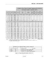
Page 178: ...SECTION 5 HYDRAULICS 5 24 JLG Lift 3121827 Figure 5 26 HydraForce Cartridge Torque Value Chart...
Page 214: ...SECTION 6 JLG CONTROL SYSTEM 6 34 JLG Lift 3121827 NOTES...
Page 257: ......

