SECTION 3 - CHASSIS & TURNTABLE
3-30
– JLG Lift –
3121827
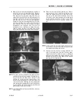
replaced. If the housing has passed this inspection
the disassembly of the motor is completed.
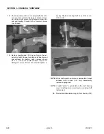
NOTE:
The depth or location of bearing/bushing (13) in rela-
tion to the housing wear plate surface and the depth
or location of bearing/bushing (19) in relation to the
beginning of bearing/bushing counter bore should be
measured and noted before removing the bearings/
bushings. This will facilitate the correct reassembly
of new bearings/bushings.
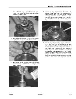
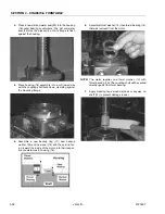
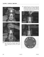
20.
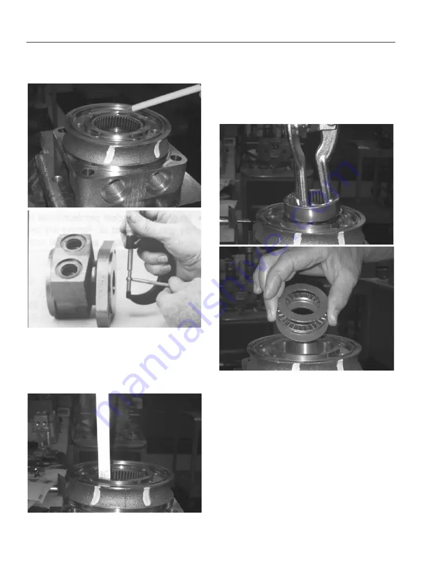
If the bearings, bushing or thrust washers must be
replaced use a suitable size bearing puller to
remove bearing/bushings (19) and (13) from hous-
ing (18) without damaging the housing. Remove
thrust washers (14) and thrust bearing (15) if they
were previously retained in the housing by bearing
(13).
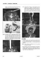
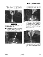
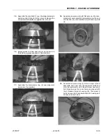
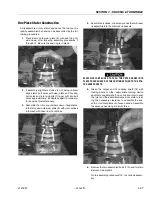
Assembly
Replace all seals and seal rings with new ones each time
you reassemble the motor unit. Lubricate all seals and
seal rings with SAE 10W40 oil or clean grease before
assembly.
NOTE:
Unless otherwise indicated, do not oil or grease
parts before assembly.
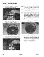
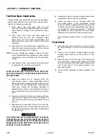
Wash all parts in clean petroleum-based solvents before
assembly. Blow them dry with compressed air. Remove
any paint chips from mating surfaces of the end cover,
commutator set, manifold rotor set, wear plate and hous-
ing and from port and sealing areas.
Summary of Contents for JLG E400AJP
Page 2: ......
Page 32: ...SECTION 1 SPECIFICATIONS 1 18 JLG Lift 3121827 NOTES...
Page 42: ...SECTION 2 GENERAL 2 10 JLG Lift 3121827 NOTES...
Page 54: ...SECTION 3 CHASSIS TURNTABLE 3 12 JLG Lift 3121827 Figure 3 3 Speed Sensor Orientation...
Page 60: ...SECTION 3 CHASSIS TURNTABLE 3 18 JLG Lift 3121827 Figure 3 7 Steering Components and Spindles...
Page 62: ...SECTION 3 CHASSIS TURNTABLE 3 20 JLG Lift 3121827 Figure 3 9 Tilt Sensor Location...
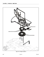
Page 86: ...SECTION 3 CHASSIS TURNTABLE 3 44 JLG Lift 3121827 Figure 3 16 Swing Components...
Page 88: ...SECTION 3 CHASSIS TURNTABLE 3 46 JLG Lift 3121827 Figure 3 18 Battery Cable Connections...
Page 90: ...SECTION 3 CHASSIS TURNTABLE 3 48 JLG Lift 3121827 Figure 3 20 On Board Generator...
Page 97: ...SECTION 3 CHASSIS TURNTABLE 3121827 JLG Lift 3 55 Figure 3 22 Generator Components...
Page 116: ...SECTION 3 CHASSIS TURNTABLE 3 74 JLG Lift 3121827 NOTES...
Page 127: ...SECTION 4 BOOM PLATFORM 3121827 JLG Lift 4 11 Figure 4 10 Boom Limit Switches...
Page 140: ...SECTION 4 BOOM PLATFORM 4 24 JLG Lift 3121827 Figure 4 13 Rotator Counterbalance Valve...
Page 178: ...SECTION 5 HYDRAULICS 5 24 JLG Lift 3121827 Figure 5 26 HydraForce Cartridge Torque Value Chart...
Page 214: ...SECTION 6 JLG CONTROL SYSTEM 6 34 JLG Lift 3121827 NOTES...
Page 257: ......


