SECTION 3 - CHASSIS & TURNTABLE
3121827
– JLG Lift –
3-37
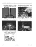
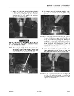
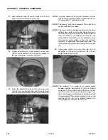
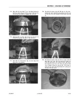
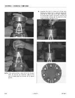
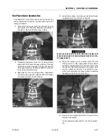
One Piece Stator Construction
A disassembled rotor stator and vanes that cannot be
readily assembled by hand can be assembled by the fol-
lowing procedures.
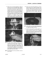
1.
Place stator onto wear plate (9) with seal ring (4)
side down, after following assembly procedures 1
through 13. Be sure the seal ring is in place.
2.
If assembly alignment studs are not being utilized,
align stator bolt holes with wear plate and housing
bolt holes and turn two bolts (1) finger tight into bolt
holes approximately 180 degrees apart to retain sta-
tor and wear plate stationary.
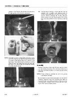
3.
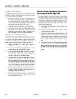
Assemble the rotor, counterbore down if applicable,
into stator, and onto wear plate (9) with rotor splines
into mesh with drive link (10) splines.
4.
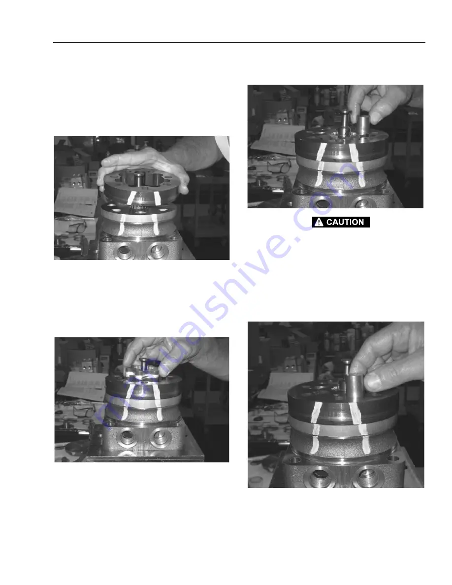
Assemble six vanes, or as many vanes that will read-
ily assemble into the stator vane pockets.
EXCESSIVE FORCE USED TO PUSH THE ROTOR VANES INTO
PLACE COULD SHEAR OFF THE COATING APPLIED TO THE STA-
TOR VANE POCKETS.
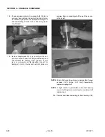
5.
Grasp the output end of coupling shaft (12) with
locking pliers or other appropriate turning device
and rotate coupling shaft, drive link and rotor to seat
the rotor and the assembled vanes into stator, creat-
ing the necessary clearance to assemble the sev-
enth or full complement of seven vanes. Assemble
the seven vanes using minimum force.
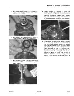
6.
Remove the two assembled bolts (1) if used to retain
stator and wear plate.
Go to assembly procedure #15, to continue assem-
bly.
Summary of Contents for JLG E400AJP
Page 2: ......
Page 32: ...SECTION 1 SPECIFICATIONS 1 18 JLG Lift 3121827 NOTES...
Page 42: ...SECTION 2 GENERAL 2 10 JLG Lift 3121827 NOTES...
Page 54: ...SECTION 3 CHASSIS TURNTABLE 3 12 JLG Lift 3121827 Figure 3 3 Speed Sensor Orientation...
Page 60: ...SECTION 3 CHASSIS TURNTABLE 3 18 JLG Lift 3121827 Figure 3 7 Steering Components and Spindles...
Page 62: ...SECTION 3 CHASSIS TURNTABLE 3 20 JLG Lift 3121827 Figure 3 9 Tilt Sensor Location...
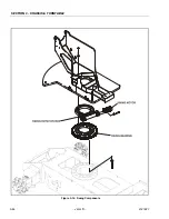
Page 86: ...SECTION 3 CHASSIS TURNTABLE 3 44 JLG Lift 3121827 Figure 3 16 Swing Components...
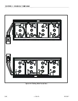
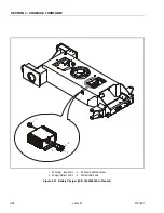
Page 88: ...SECTION 3 CHASSIS TURNTABLE 3 46 JLG Lift 3121827 Figure 3 18 Battery Cable Connections...
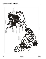
Page 90: ...SECTION 3 CHASSIS TURNTABLE 3 48 JLG Lift 3121827 Figure 3 20 On Board Generator...
Page 97: ...SECTION 3 CHASSIS TURNTABLE 3121827 JLG Lift 3 55 Figure 3 22 Generator Components...
Page 116: ...SECTION 3 CHASSIS TURNTABLE 3 74 JLG Lift 3121827 NOTES...
Page 127: ...SECTION 4 BOOM PLATFORM 3121827 JLG Lift 4 11 Figure 4 10 Boom Limit Switches...
Page 140: ...SECTION 4 BOOM PLATFORM 4 24 JLG Lift 3121827 Figure 4 13 Rotator Counterbalance Valve...
Page 178: ...SECTION 5 HYDRAULICS 5 24 JLG Lift 3121827 Figure 5 26 HydraForce Cartridge Torque Value Chart...
Page 214: ...SECTION 6 JLG CONTROL SYSTEM 6 34 JLG Lift 3121827 NOTES...
Page 257: ......


