SECTION 3 - MACHINE CONTROLS AND INDICATORS
3121664
– JLG Lift –
3-15
4.
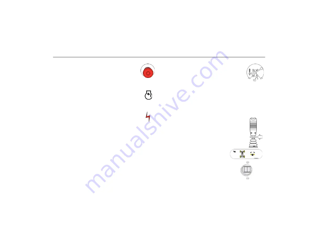
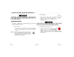
Power/Emergency Stop Switch
A two-position red mushroom shaped switch
furnishes power to PLATFORM Controls when
pulled out (on). When pushed in (off ), power is
shut off to the platform functions.
5.
Start/Auxiliary Power
When pushed forward, the switch energizes
the starter motor to start the engine.
The Auxiliary Power control switch energizes
the electrically operated hydraulic pump.
(Switch must be held ON for duration of auxil-
iary pump use.)
The auxiliary pump functions to provide sufficient oil flow to
operate the basic machine functions should the main pump
or engine fail. The auxiliary pump will operate tower boom
lift, tower telescope, main boom lift, main telescope and
swing.
6.
Drive Orientation Override
When the boom is swung over the rear tires
or further in either direction, the Drive Orien-
tation indicator will illuminate when the drive
function is selected. Push and release the
switch, and within 3 seconds move the Drive/Steer control
to activate drive or steer. Before driving, locate the black/
white orientation arrows on both the chassis and the plat-
form controls. Move the drive controls in a direction match-
ing the directional arrows for the intended direction of
travel.
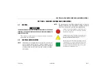
NOTE:
To operate the Drive joystick, pull up on the lock-
ing ring below the handle.
NOTE:
The Drive joystick is spring loaded and will auto-
matically return to neutral (off) position when
released.
7.
Drive/Steer
Push forward to drive forward,
pull back to drive in reverse.
Steering is accomplished via a
thumb-activated rocker switch on
the end of the steer handle.
Summary of Contents for JLG 520AJ
Page 2: ......
Page 26: ...SECTION 1 SAFETY PRECAUTIONS 1 14 JLG Lift 3121664 NOTES ...
Page 60: ...SECTION 3 MACHINE CONTROLS AND INDICATORS 3 22 JLG Lift 3121664 NOTES ...
Page 68: ...SECTION 4 MACHINE OPERATION 4 8 JLG Lift 3121664 Figure 4 3 Grade and Side Slopes ...
Page 75: ...SECTION 4 MACHINE OPERATION 3121664 JLG Lift 4 15 Figure 4 5 Lifting and Tie Down Chart ...
Page 76: ...SECTION 4 MACHINE OPERATION 4 16 JLG Lift 3121664 Figure 4 6 Decal Location Sheet 1 of 6 ...
Page 77: ...SECTION 4 MACHINE OPERATION 3121664 JLG Lift 4 17 Figure 4 7 Decal Location Sheet 2 of 6 ...
Page 78: ...SECTION 4 MACHINE OPERATION 4 18 JLG Lift 3121664 Figure 4 8 Decal Location Sheet 3 of 6 ...
Page 79: ...SECTION 4 MACHINE OPERATION 3121664 JLG Lift 4 19 Figure 4 9 Decal Location Sheet 4 of 6 ...
Page 80: ...SECTION 4 MACHINE OPERATION 4 20 JLG Lift 3121664 Figure 4 10 Decal Location Sheet 5 of 6 ...
Page 81: ...SECTION 4 MACHINE OPERATION 3121664 JLG Lift 4 21 Figure 4 11 Decal Location Sheet 6 of 6 ...
Page 88: ...SECTION 5 EMERGENCY PROCEDURES 5 4 JLG Lift 3121664 NOTES ...
Page 108: ...SECTION 6 GENERAL SPECIFICATIONS OPERATOR MAINTENANCE 6 20 JLG Lift 3121664 NOTES ...
Page 110: ......
Page 111: ......


