SECTION 4 - BOOM & PLATFORM
4-20
– JLG Lift –
3121623
4.6
BOOM ROTATION SENSOR ASSEMBLY - X23JP -
X700AJ
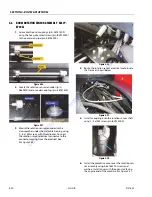
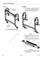
1.
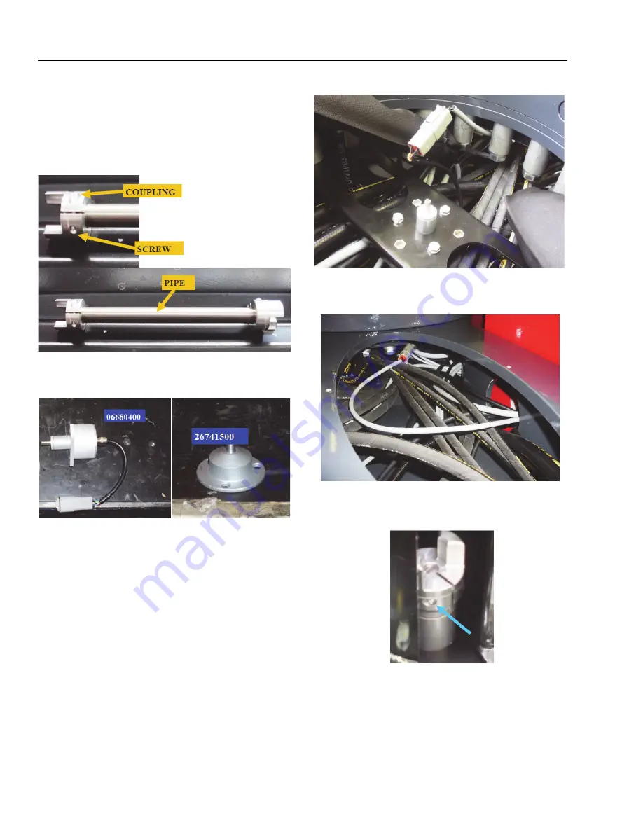
Assemble the end couplings (p/n-26741500)
using the hex galvanized screws (p/n-BV013000)
to the extension pipe (p/n-06745900).
Figure 4-26.
2.
Locate the rotation sensor (encoder) (p/n-
0660400) and encoder coupling (p/n-26741500).
Figure 4-27.
3.
Mount the rotation sensor (encoder) to the
crossmember under the turntable bearing using
3 - 6 x 12M screws with threadlocker. Connect
the rotation sensor electrical connector to the
connector coming from the electrical box.
Figure 4-28.
4.
Route the rotation sensor electrical cable inside
the frame as shown below.
Figure 4-29.
5.
Install a coupling onto the rotation sensor shaft
using 1 - 3x12M screw (p/n-BV013000).
Figure 4-30.
6.
Install the protective cover over the rotation sen-
sor assembly using 3-6x16M TE screws and
washers. Install cover with the open slot facing
the engine end of the machine.
Go to
Discount-Equipment.com
to
order your
parts

