Optical Scientific Inc
OFS 2000CW User’s Guide
P/N 1910-905
Rev. 03/28/13
6
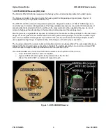
1.4 OFS 2000CW Receiver (RX) Unit
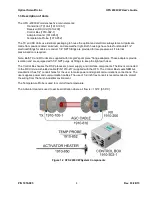
The RX Unit, P/N 1910-200 is equipped at the factory with an interconnecting cable for the AGC option.
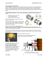
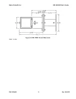
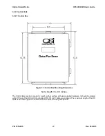
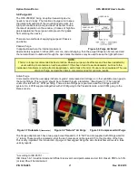
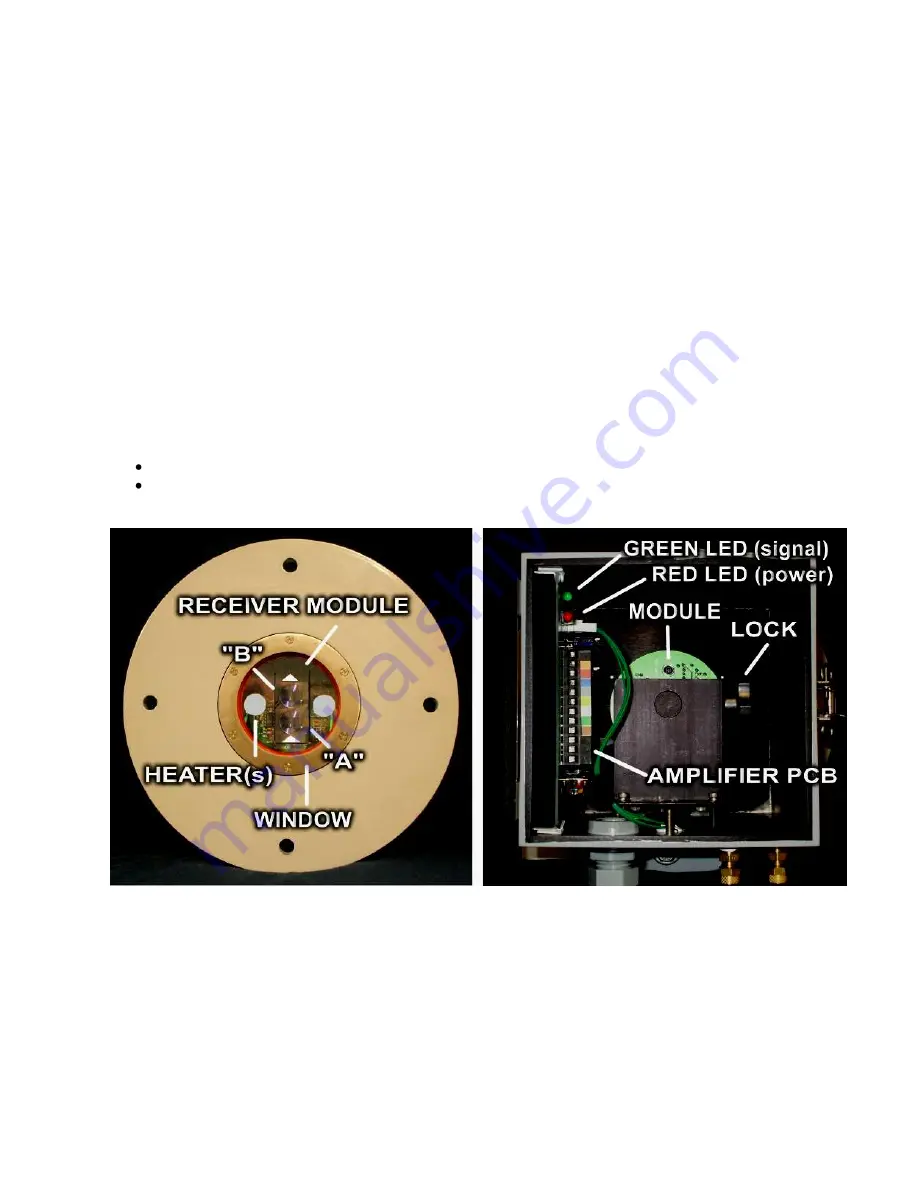
The Receiver consists of two major parts, the housing and the flange adapter (spool piece). Figure 1.4
illustrates the major components of the RX unit.
The OFS TX and RX units (with integral spool piece) are
designed to mate to a 150#, 4” ANSI flange as is
commonly used in commercial applications. The flange adapter (spool piece) is provided for this purpose. It
also provides thermal isolation from the air flow to be measured and, when supplied with purge air, an air
curtain to help keep the atmosphere in the mounting nozzles clear and the windows clean.
Mounting screws and gaskets are supplied for installing the Transmitter and flange adapter on the customer’s
flange. A silicone gasket is provided between the housing and the flange adapter to provide a weather-tight
seal. A 9-inch diameter Kevlar gasket is provided for the user to place between the flange adapter and the
user supplied mating flange. Complete sealing of the flange is critical for proper operation.
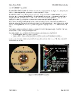
The housing contains the receiver optics and amplifier electronics subassemblies. The optics assembly is pre-
aligned in the factory and needs no focusing in the field. The optical assembly is mounted on a circular PCB
which is rotated to align the twin photodetectors with the direction of flow.
Two indicator LEDs are provided on the PCB to indicate correct operation of the TX Unit:
A red LED is ON when AC power is supplied.
A green LED is ON when light is being received from the TX Unit.
(Note: This LED is NOT an indicator of signal strength.
Figure 1.4 OFS 2000CW Receiver


