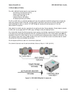
Optical Scientific Inc
OFS 2000CW User’s Guide
P/N 1910-905
Rev. 03/28/13
7
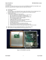
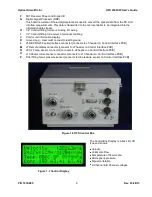
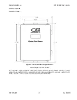
1.5 Control Box
1910-302-1 Control Box is housed in an enclosure that meets NEMA-4 standards The Control Box may be
hard-
wired using either cables or flexible conduit at the customer’s discretion.
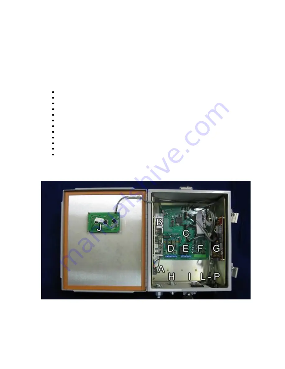
A
AC Power connection J1
B
Power Supply
The OFS contains a universal input DC power supply that operates with input voltages from 100 to
240 VAC, 50/60 Hz. This allows the unit to operate with all line voltages world-wide.
C
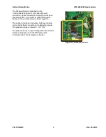
Control/Interface Board
Central point for all of the OFS interconnections.
DC Power distribution for internal components and OFS Receiver
TB1 connections for the Control Box to the RX Unit. [F]
TB2 connections for the fault relays, and optional Calibration [E]
TB3 connections for 4-20 mA current loops.[D]
J2, J3, J4 DSP data interconnects
J5 DB9 Serial Data I/O (connects to enclosure bottom [J5])
J6 connections for enclosure cover display [L]
J7 Remote display connector (connects to enclosure bottom [J7])
J8 Factory test connector
J9 Air Temperature connects to enclosure bottom [J9]
J10 Heater Current Sensor connects to enclosure bottom [J10]
U6 Pressure Sensor connects to filter fitting “Pressure Port” at enclosure bottom
D
TB3 4-20mA Current Loop Outputs [See Sections 3.12 and Section 4.2.4]
E
TB2 Fault Relay, Cal Relay & External Cal Check [See Section 3.13]
Figure 1.5 OFS 2000CW Control Box


