Optical Scientific Inc
OFS 2000CW User’s Guide
P/N 1910-905
Rev. 03/28/13
8
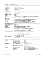
F
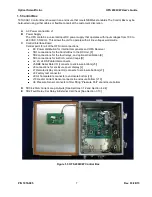
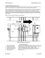
TB1 Receiver Power and Signal I/O
G
Digital Signal Processor (DSP)
This board is a state-of-the-art digital processor used to convert the optical data from the RX Unit
into flow measurements. This data is transmitted to the microcontroller to be integrated into the
information data stream.
H
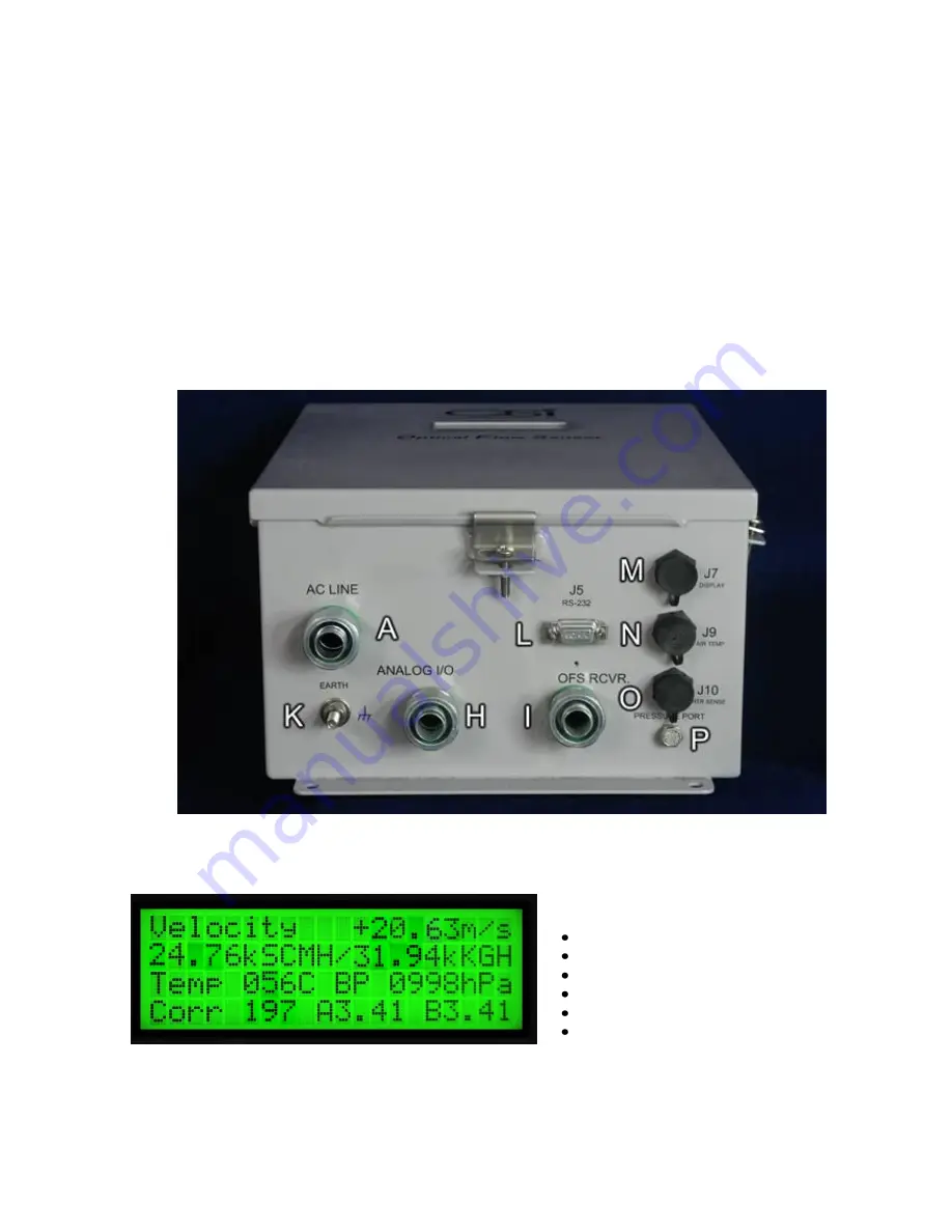
1/2” Conduit fitting for User’s Analog I/O wiring
I
1/2” Conduit fitting for receiver interconnect cabling
J
Control unit information display
K
Ground Lug
– User must connect to Earth ground.
L
J5 DB9 RS-232 serial interface connector [connects to J5 header on Control Interface PCB]
M
J7 Remote display connector [connects to J7 header on Control Interface PCB]
N
J9 Air Temp. sensor connector [connects to J9 header on Control Interface PCB]
O
J10 Heater current sensor connector [connects to J10 header on Control Interface PCB]
P
Filter fitting for air pressure sensor [connects to U6 pressure sensor on Control Interface PCB]
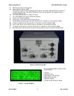
Figure 1.6 OFS Control Box
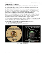
The Control Box Display is a back lit LCD
type and shows:
Velocity
Volumetric Flow
Temperature of flow media
Atmospheric pressure
Signal correlation
A Channel & B Channel voltages
Figure 1.7 Control Display


